Bringing Collections to the Street
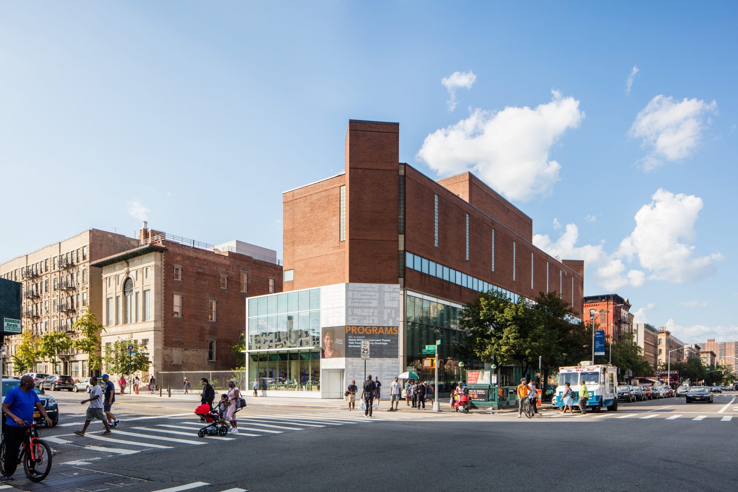
The Schomburg Center for Research in Black Culture
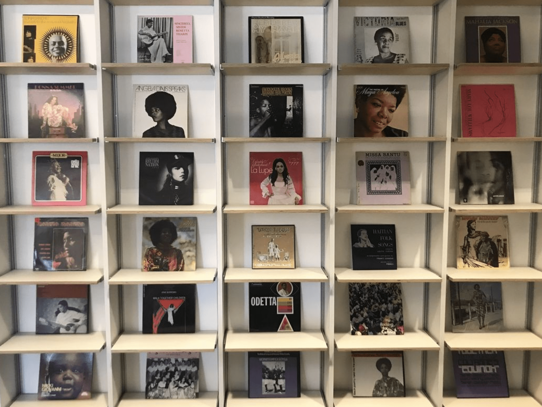
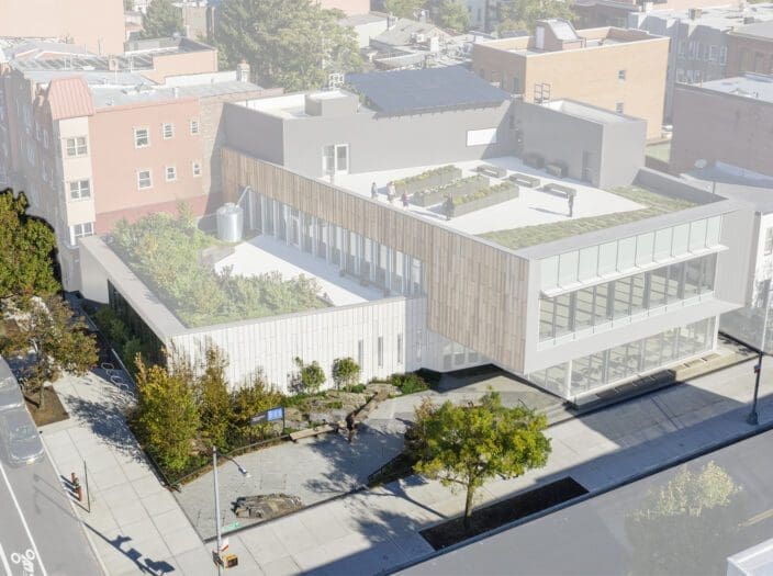
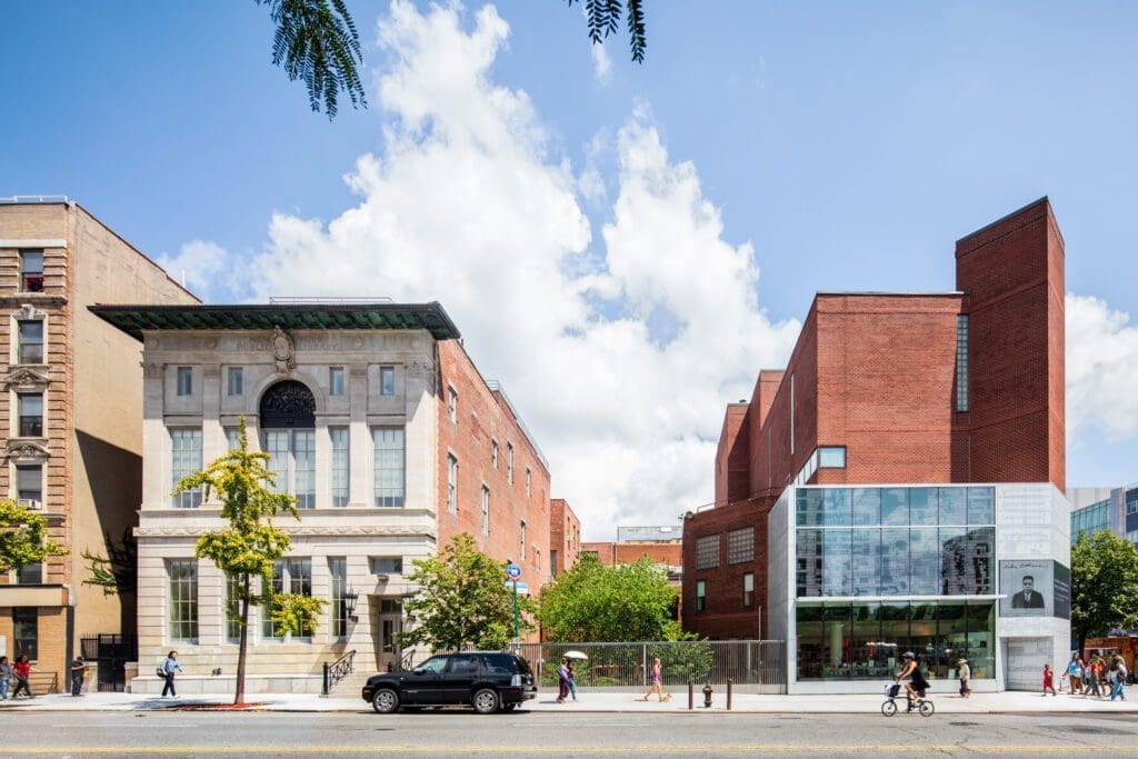
Dedicated to the research, collection, and preservation of information and materials related to the African Diaspora, the Schomburg Center for Research in Black Culture is among the world’s leading research centers predicated on preserving the history of the culture of the people of African descent. Located in Harlem, New York City, the Schomburg Center houses a vast collection of books, manuscripts, photographs, art, and artifacts that celebrate the contributions and experiences of Black individuals and communities worldwide.
With the objective of making the collection more accessible to the public, our design process explores a variety of unique ways to bring the essence of the center out to the street. Our work in these spaces is imbued with details that seek to forge connections between the inner activities of the center, and the surrounding Harlem Community.
Building History

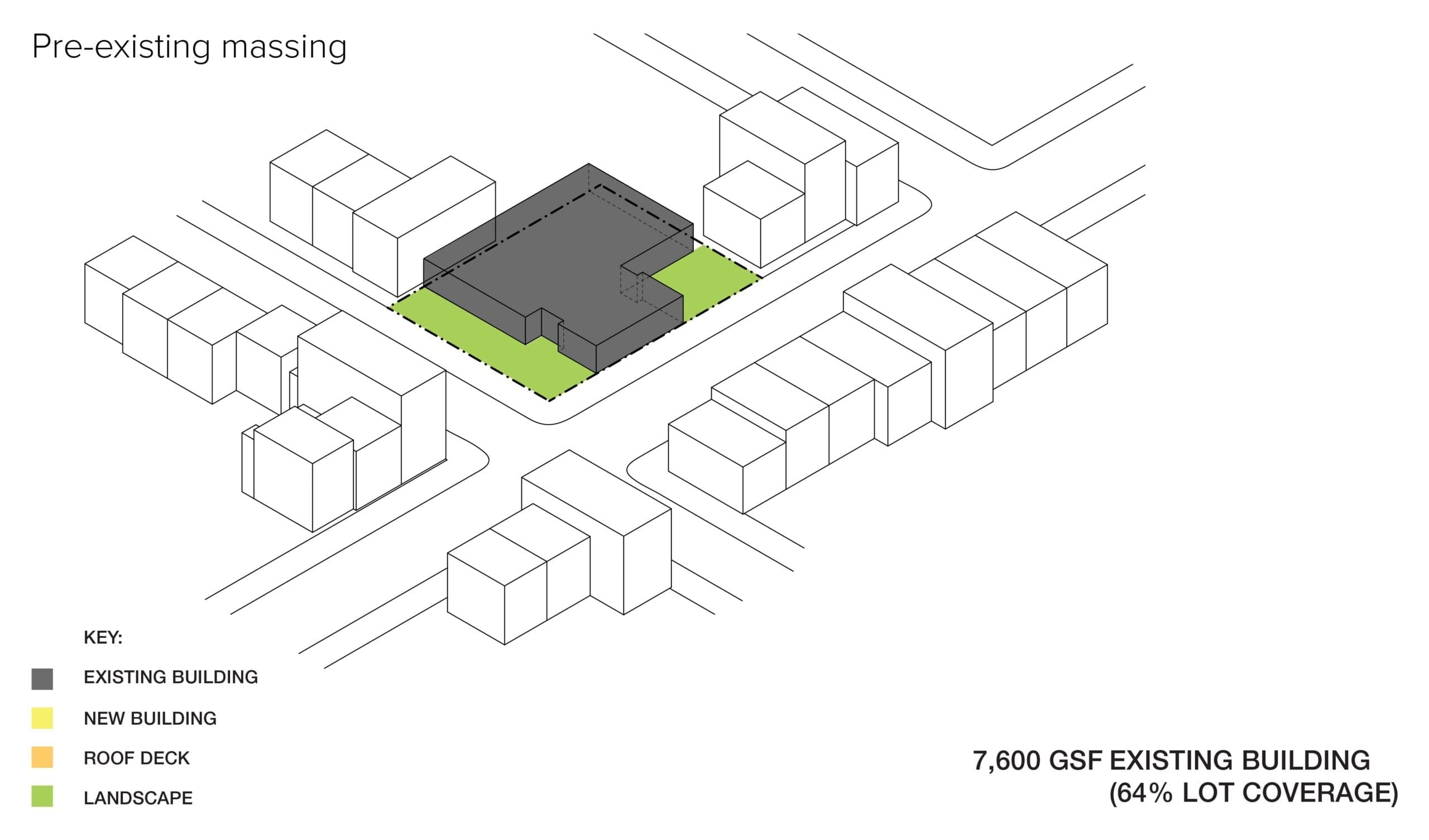
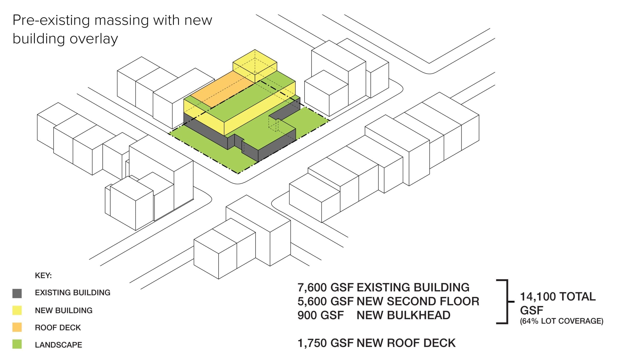
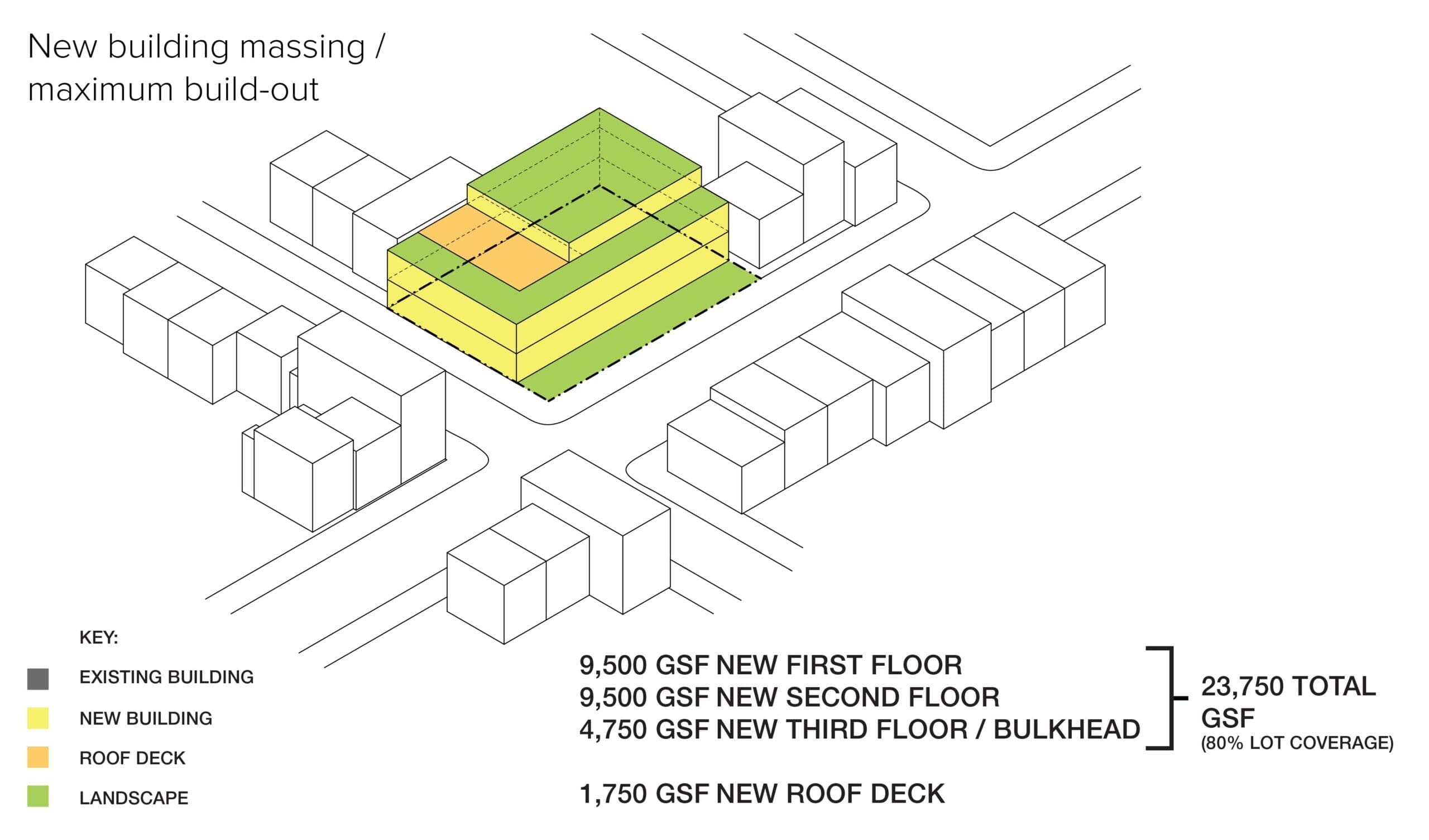
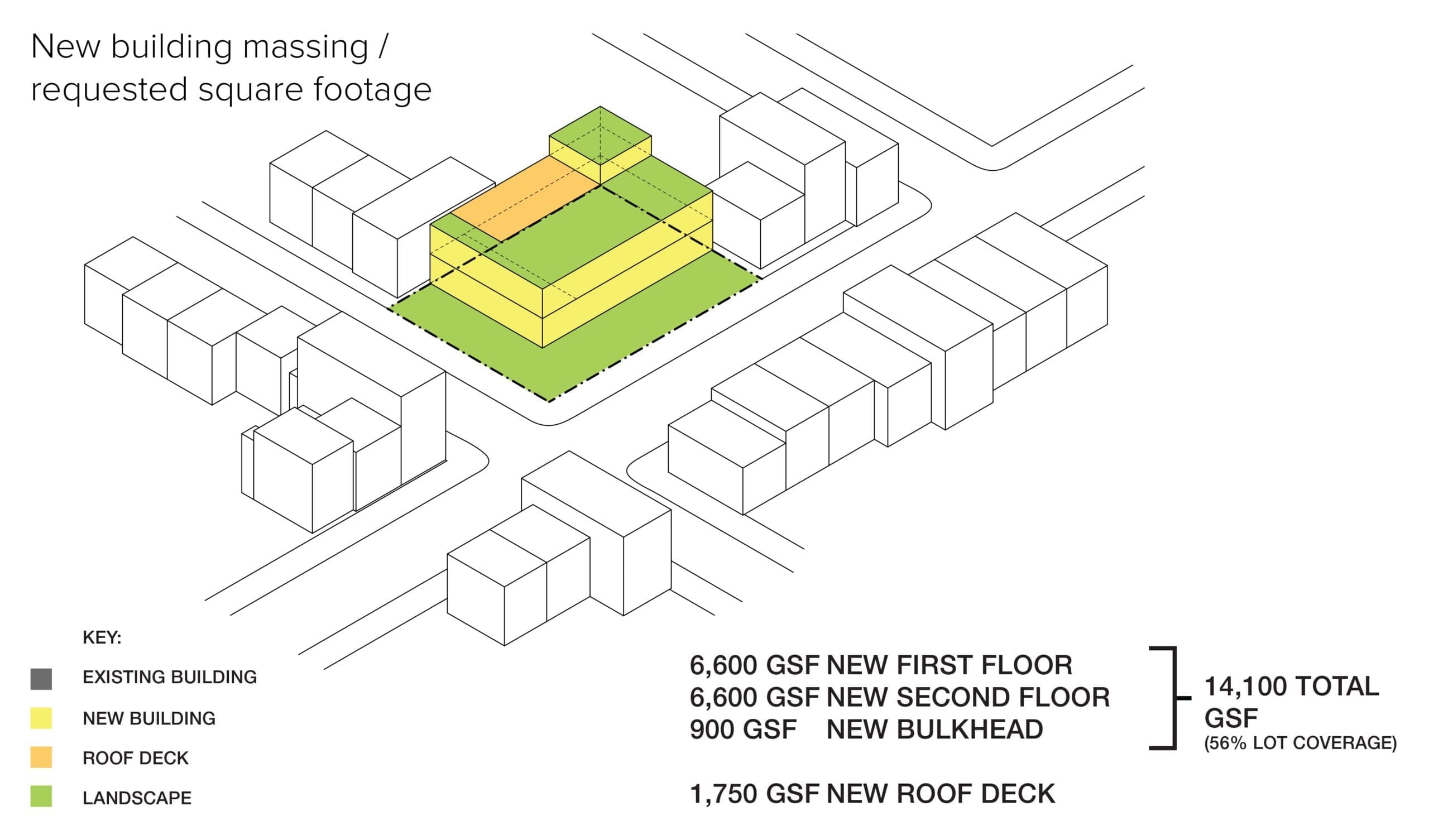
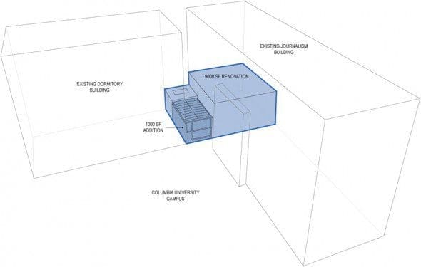
Project Scope
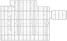
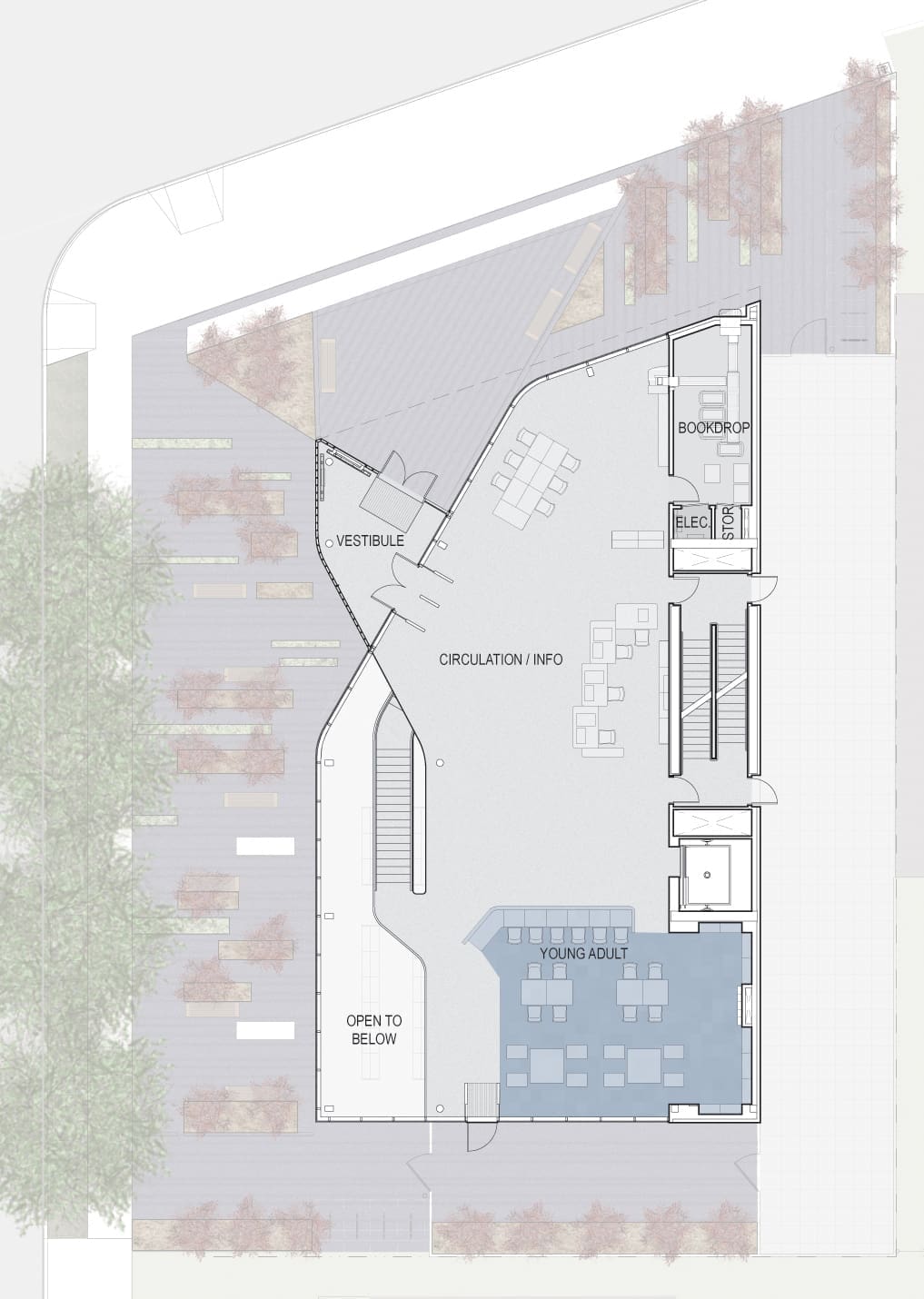
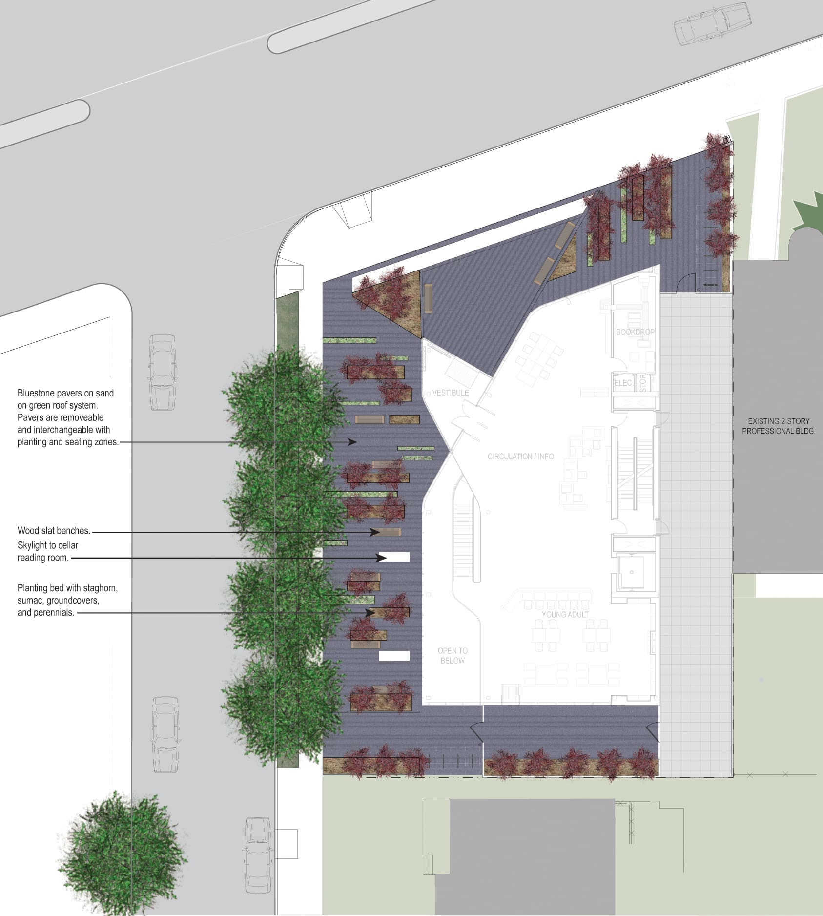
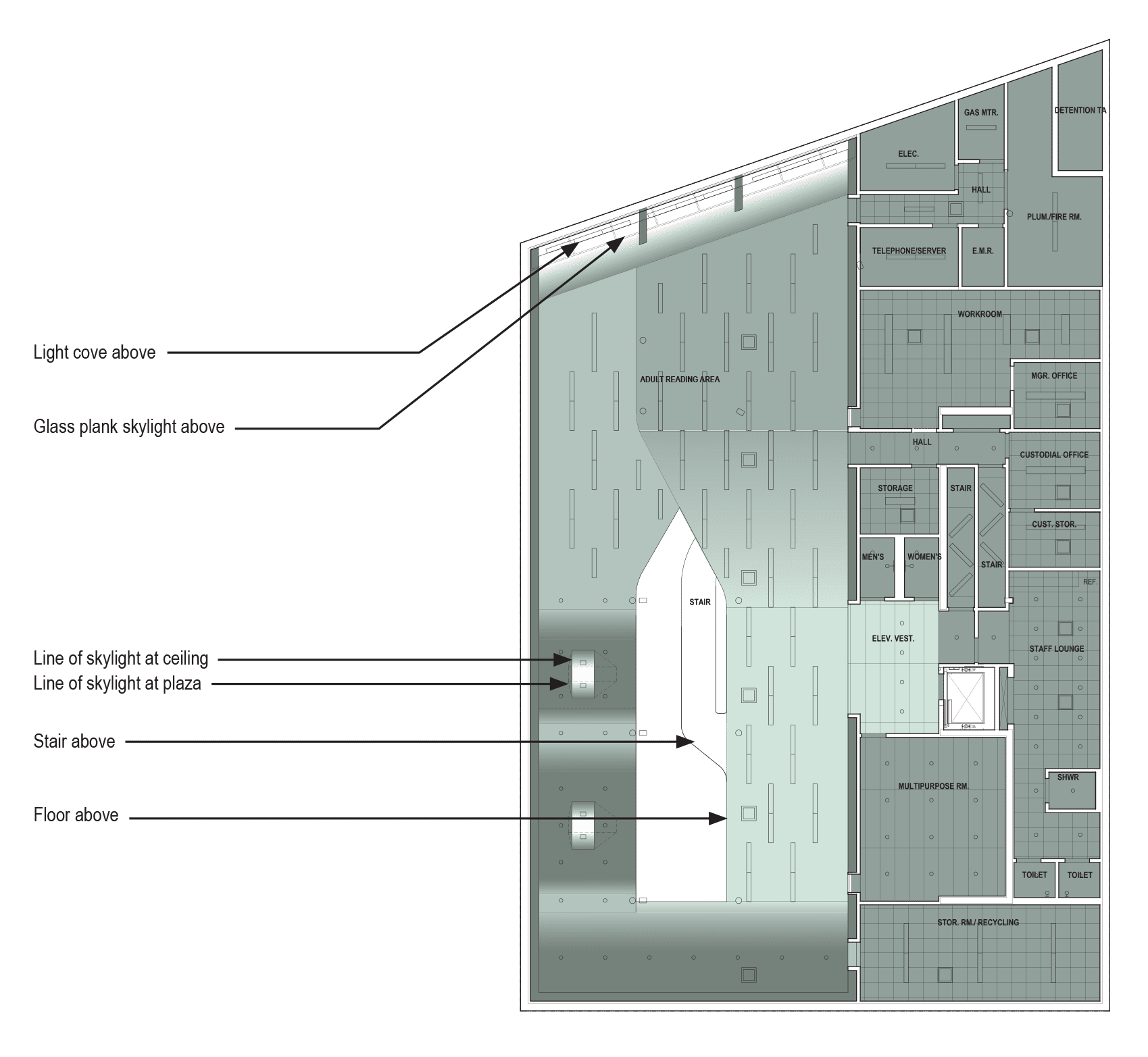
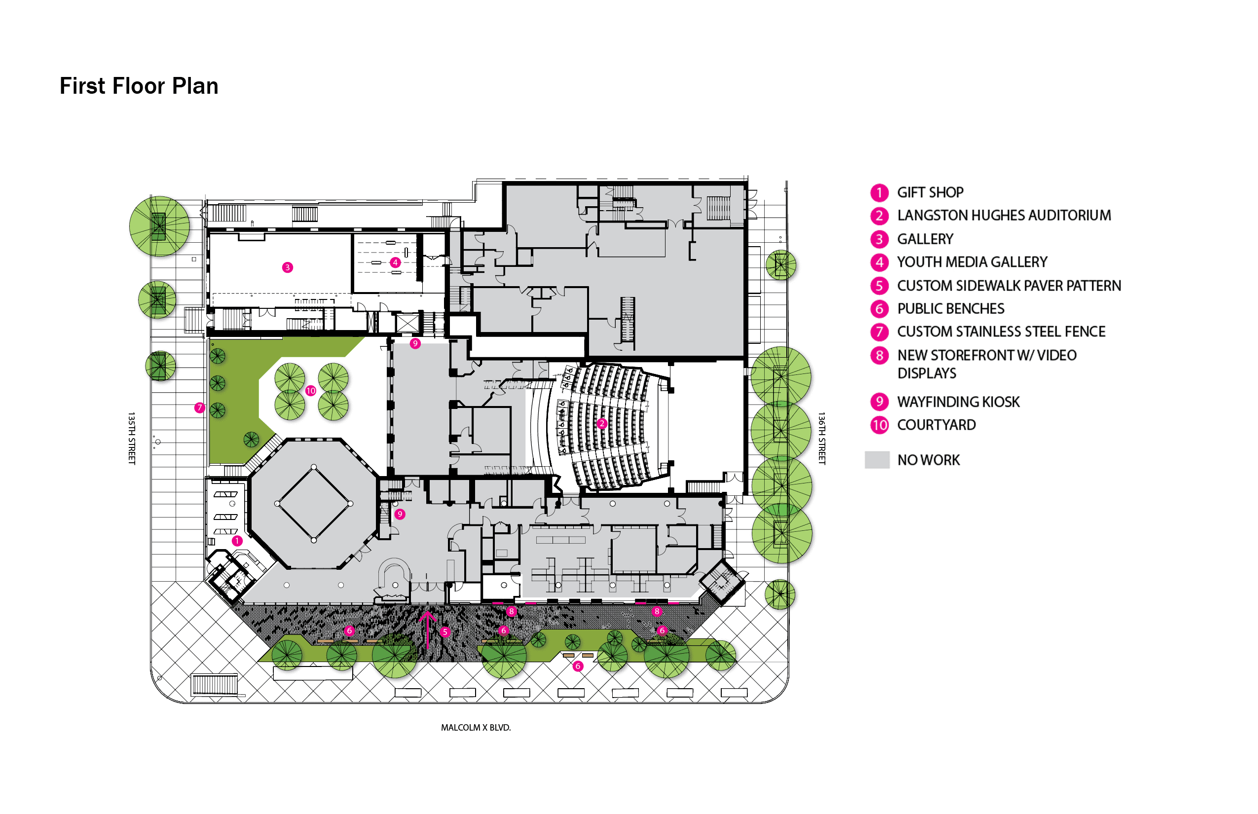
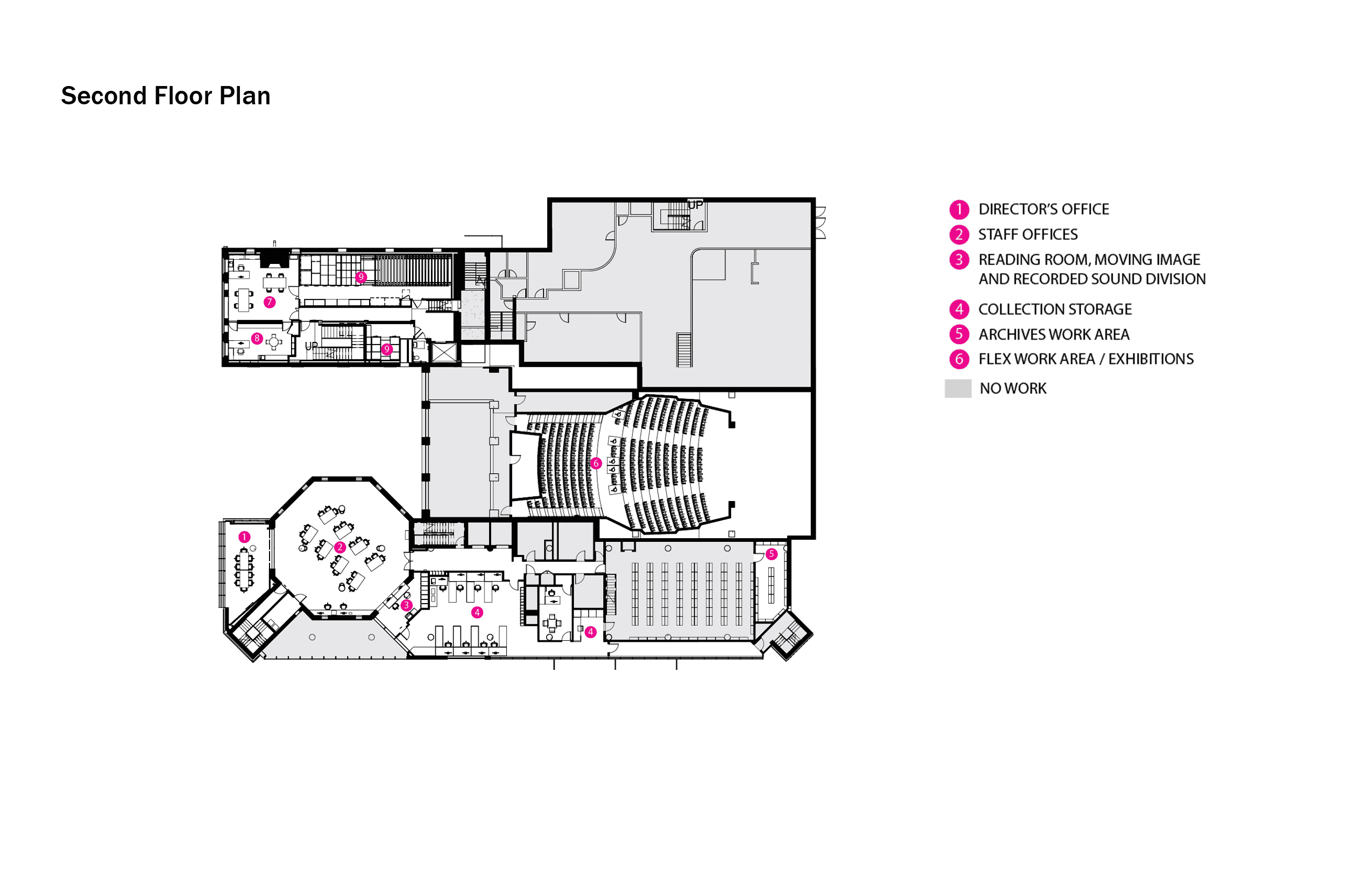
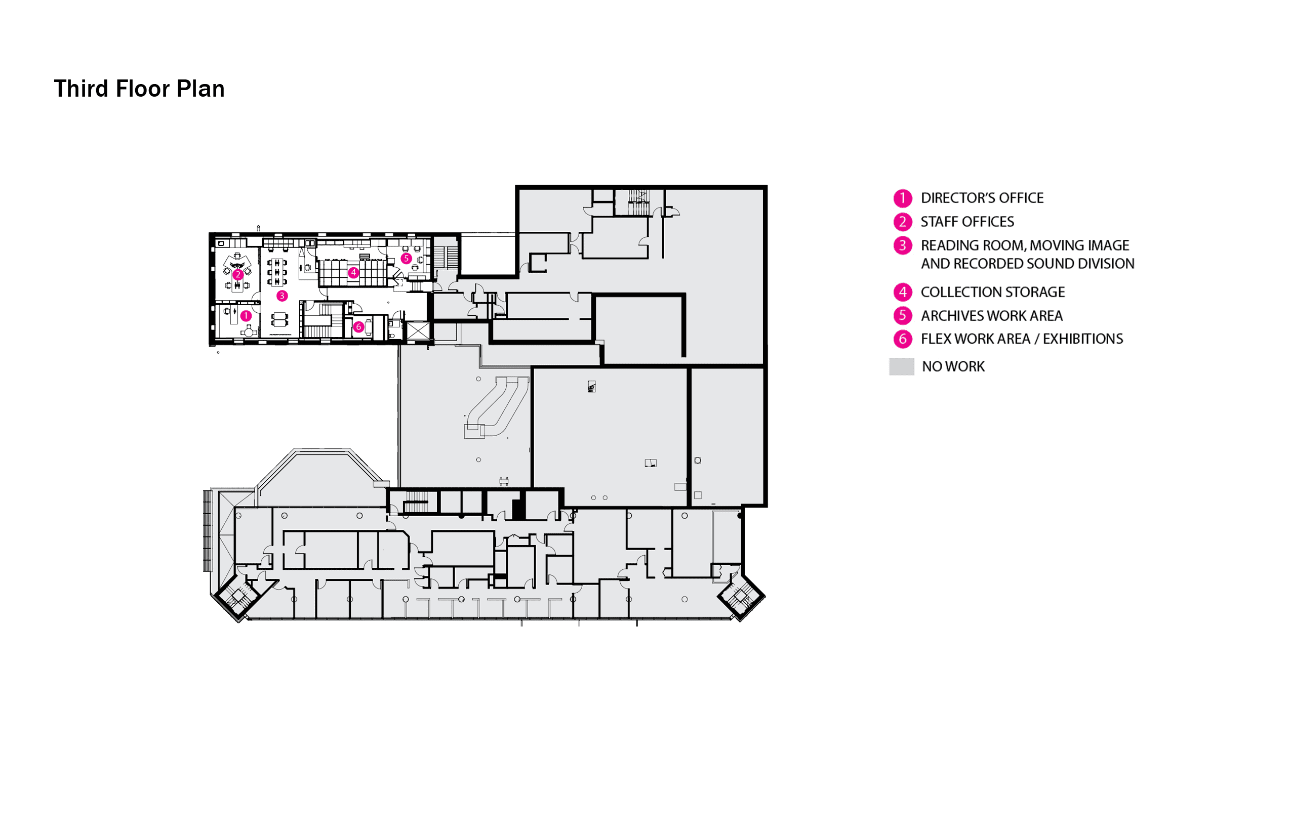
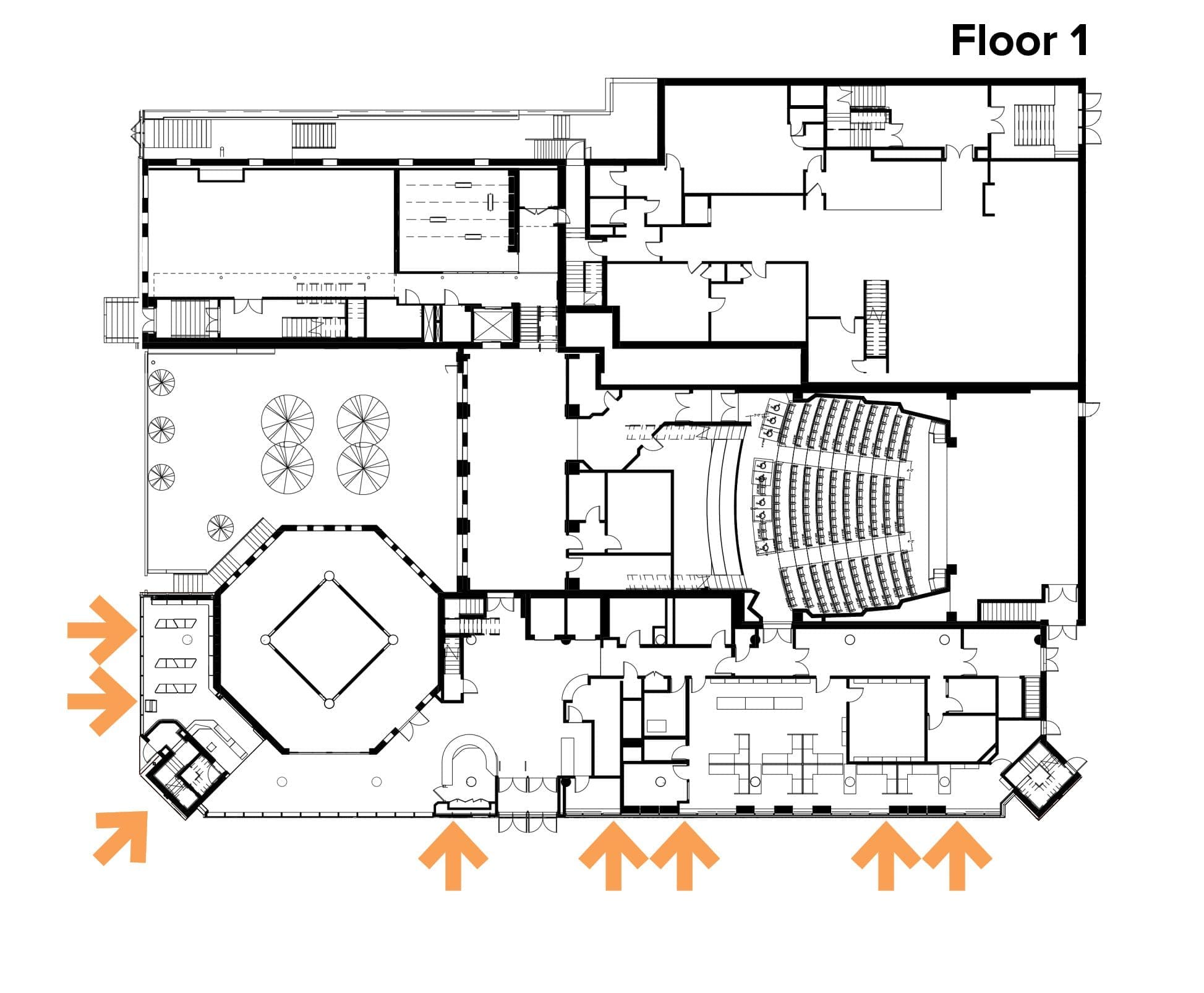
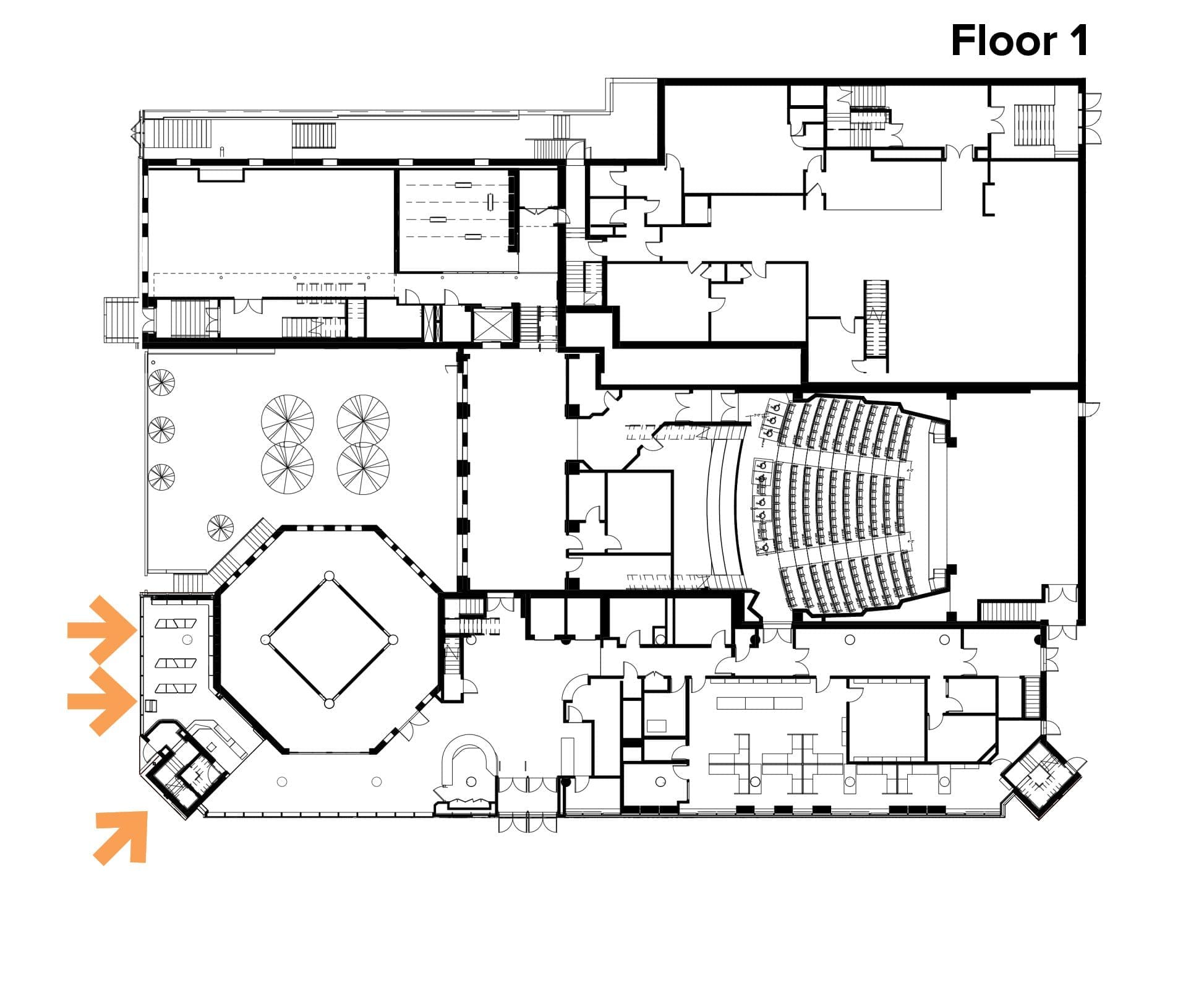
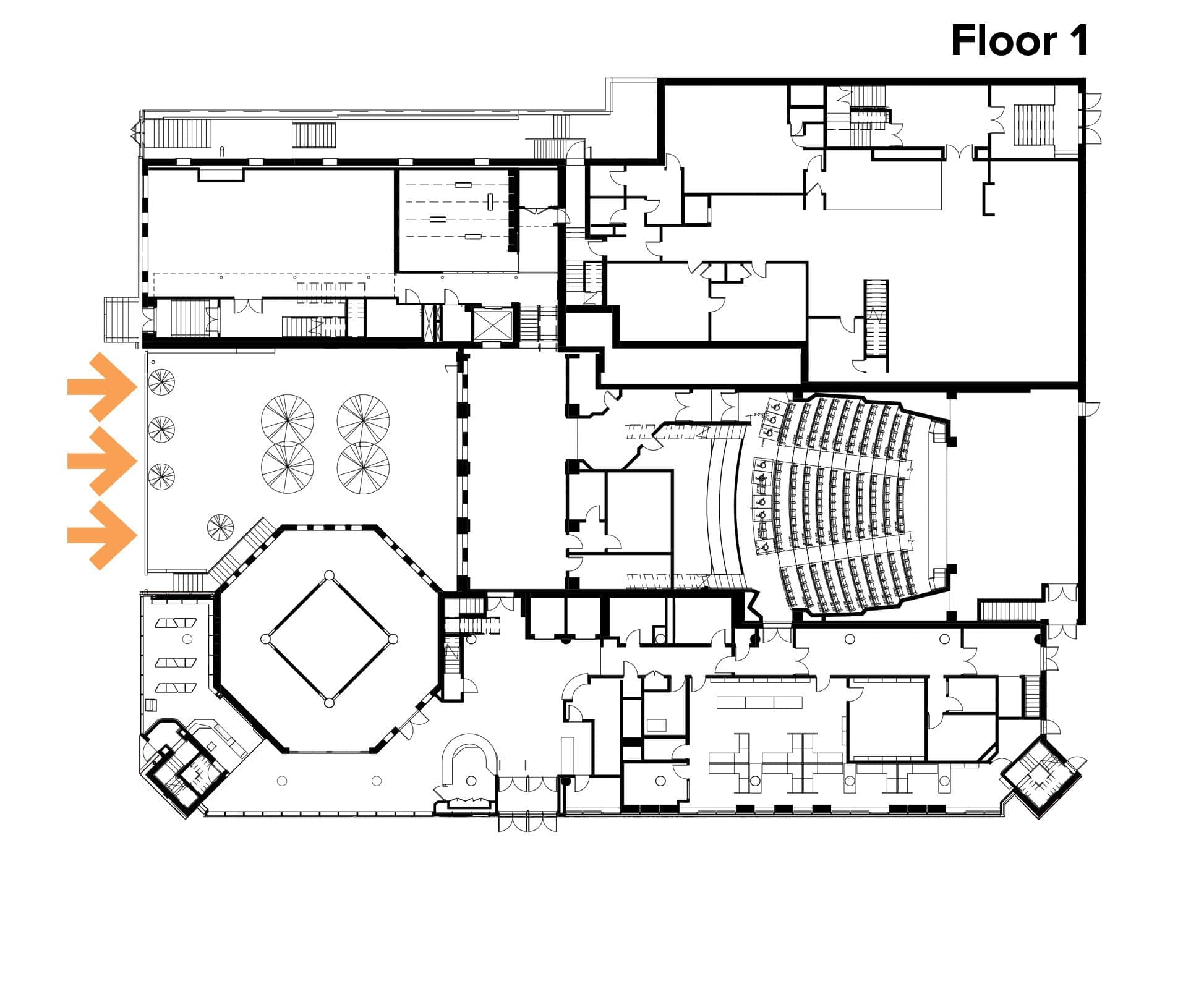
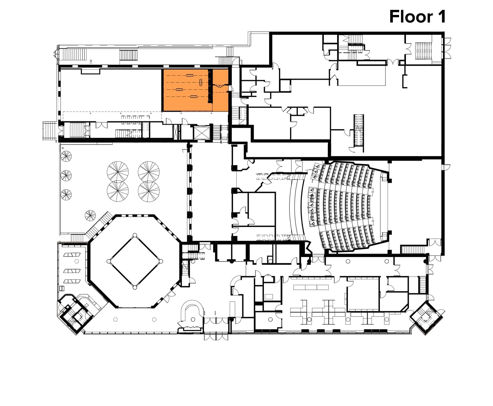
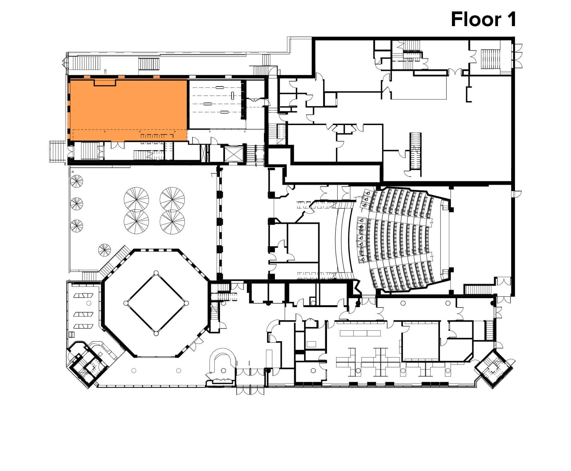
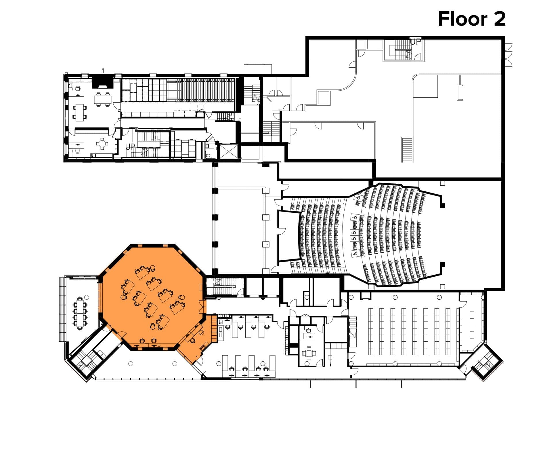
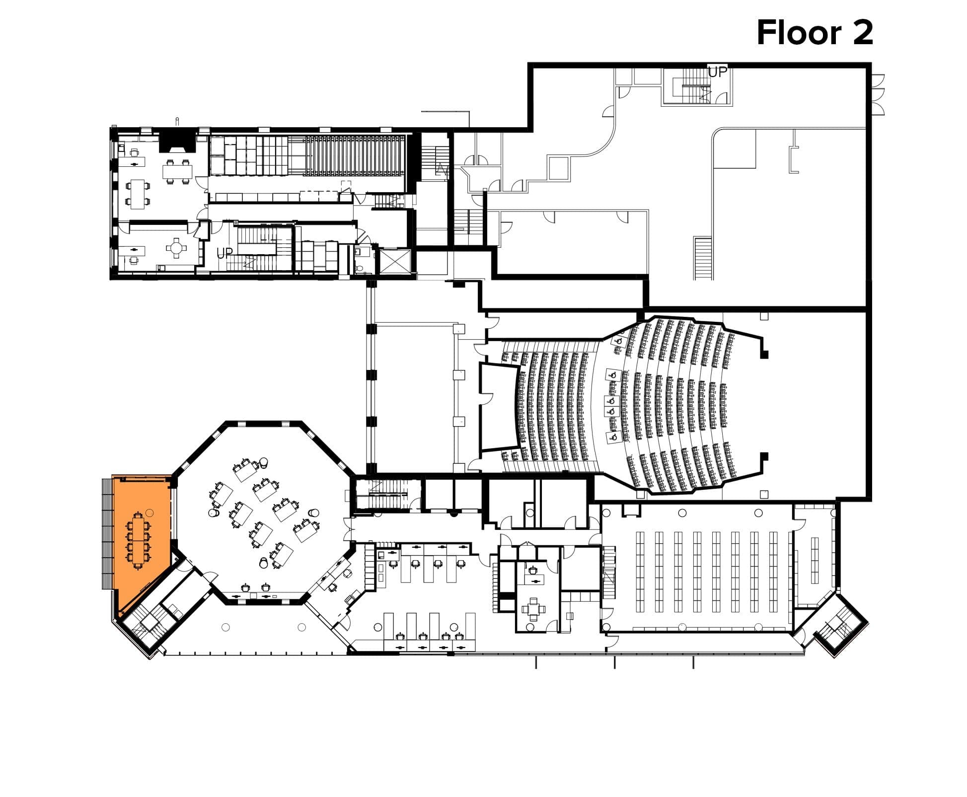
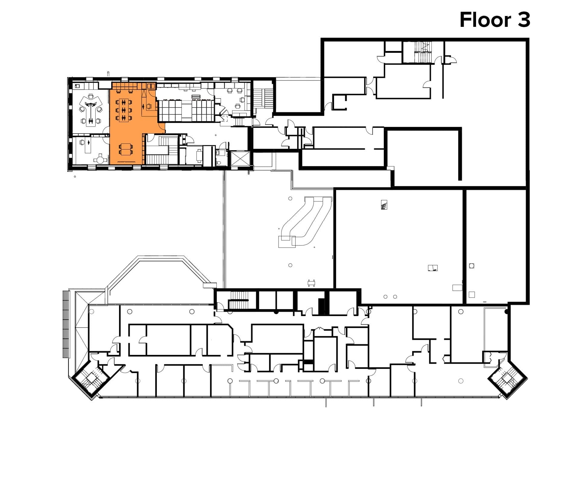
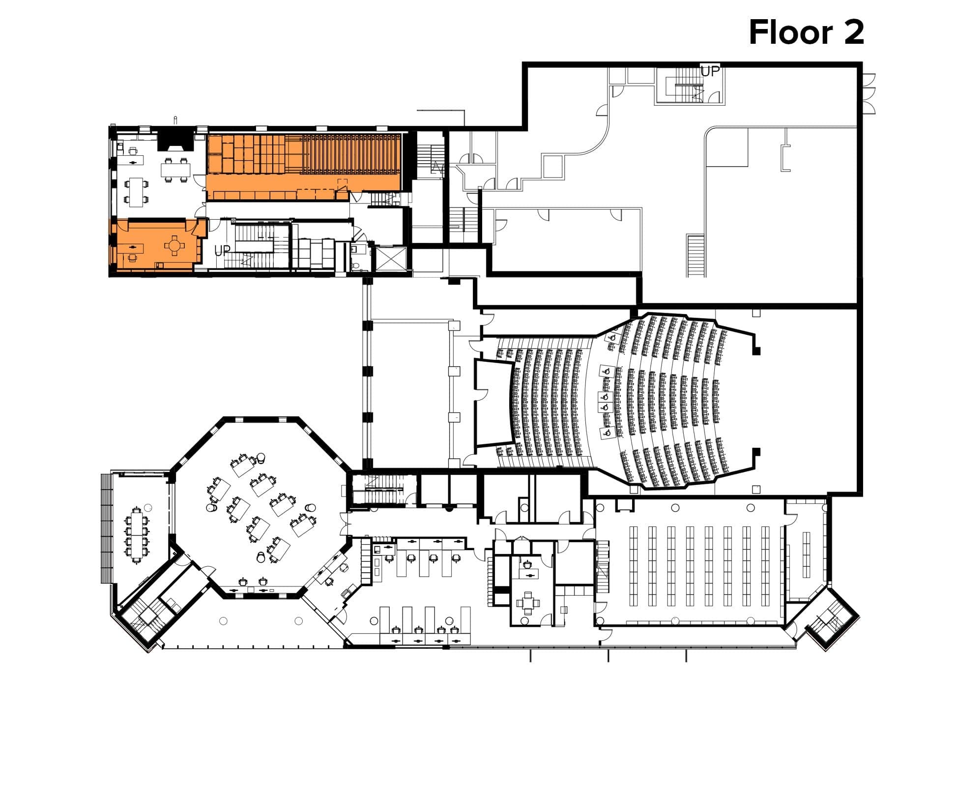
Schomburg Center Floor Plans
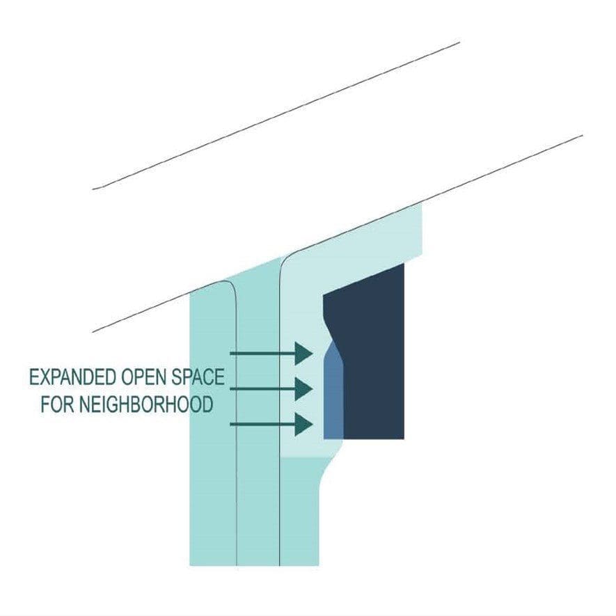
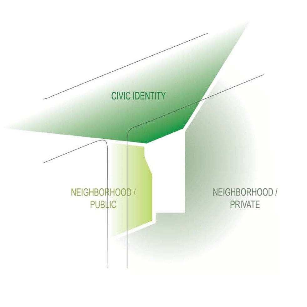
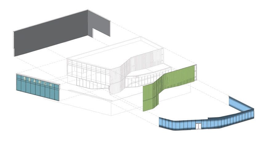
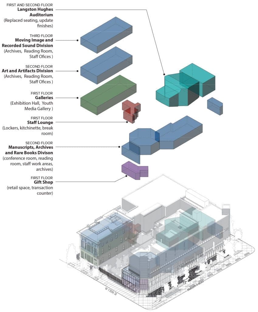
Schomburg Center Program Diagram
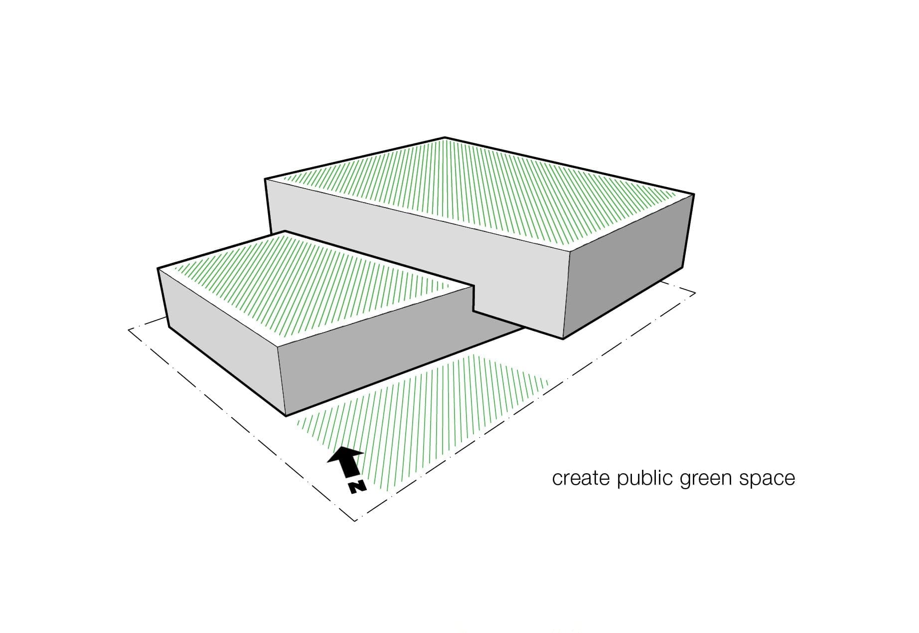
Bringing the Collection to the Street
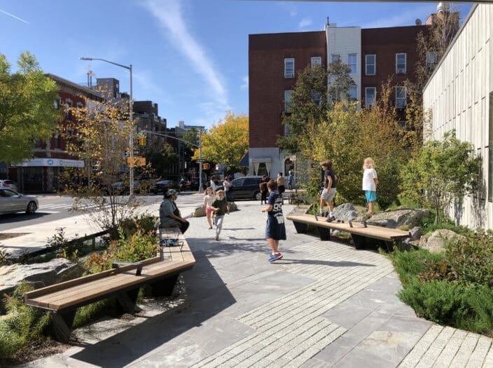
One of the key design objectives of this project was to enhance how the Schomburg Center interfaces with the public and with the surrounding Harlem community. While Schomburg’s collections are world renowned, its leadership believed that many members of the local community—especially young people—did not know what was inside the building.
Our project brings the collection and the activities of Schomburg to the street through several architectural interventions along 135th Street and Malcolm X Boulevard.
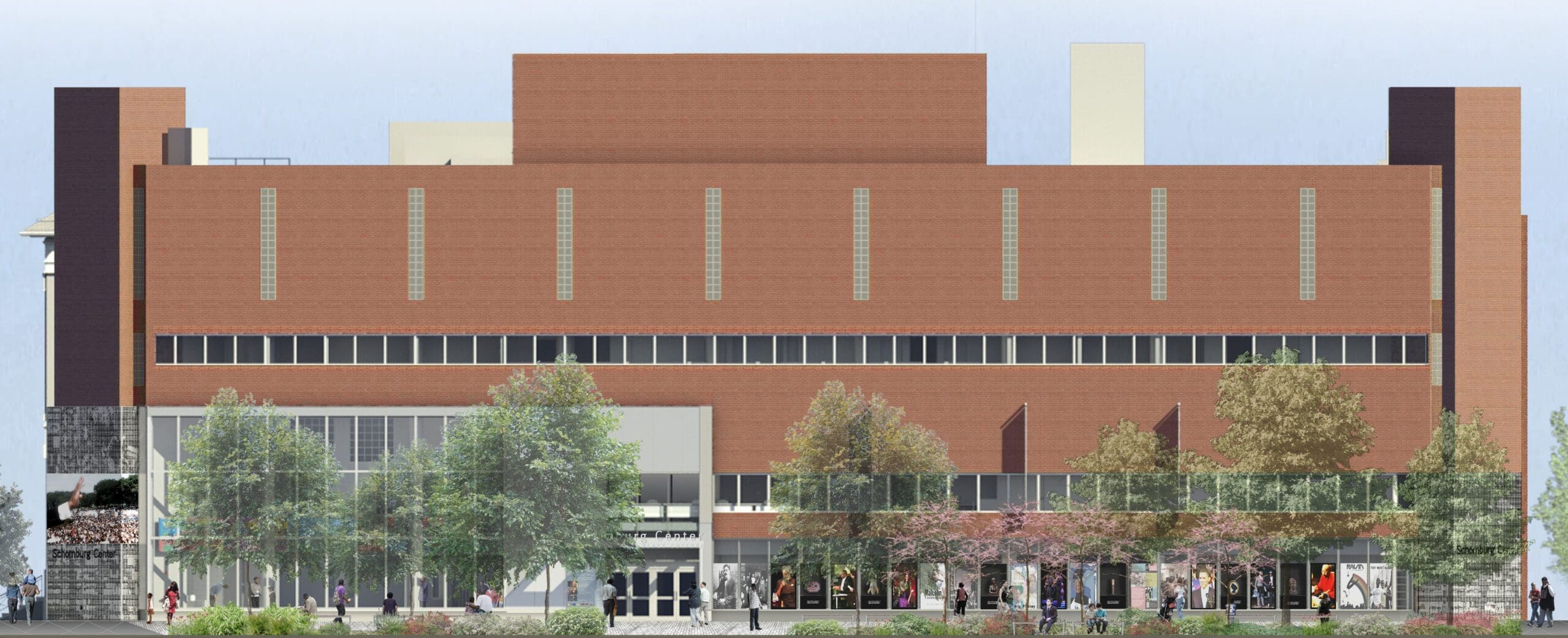
Building Interface
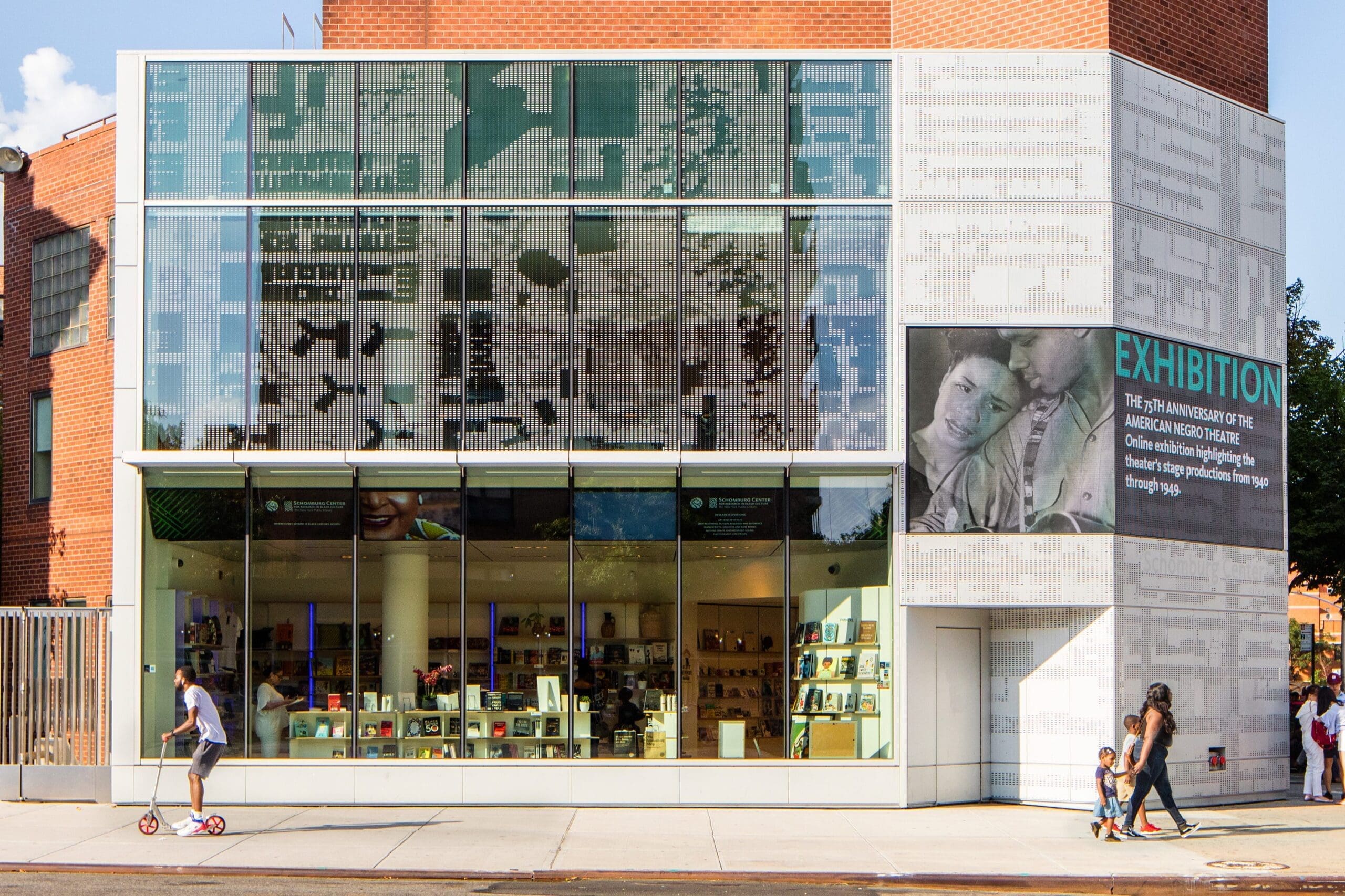
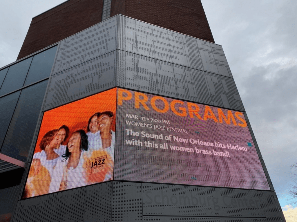
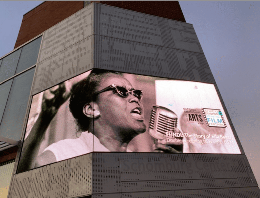
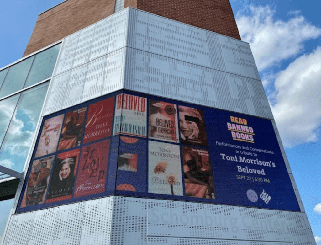
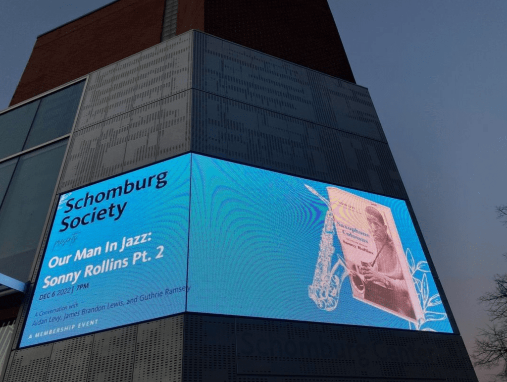
Starting along 135th street and turning the corner to continue along Malcolm X Boulevard, we integrated a series of digital screens into the building facade. These monitors display collection content and event announcements to passersby. The largest of these display screens wraps the corner of the building’s tower to entice and welcome visitors from a distance. They were designed so that Schomburg’s staff can easily change their content, allowing the facade to remain dynamic and relevant. These displays announce Schomburg as more than just a prestigious research facility. Rather, they reveal that it is also a place to listen to live music, to browse comics, and to engage with art.
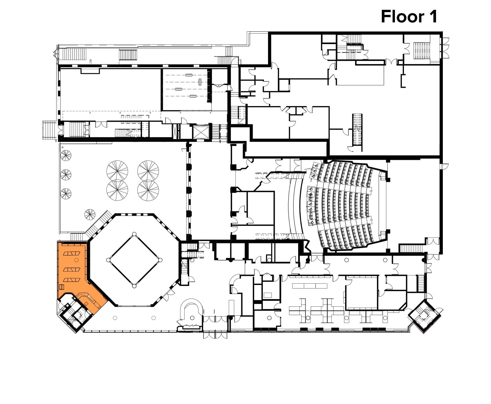
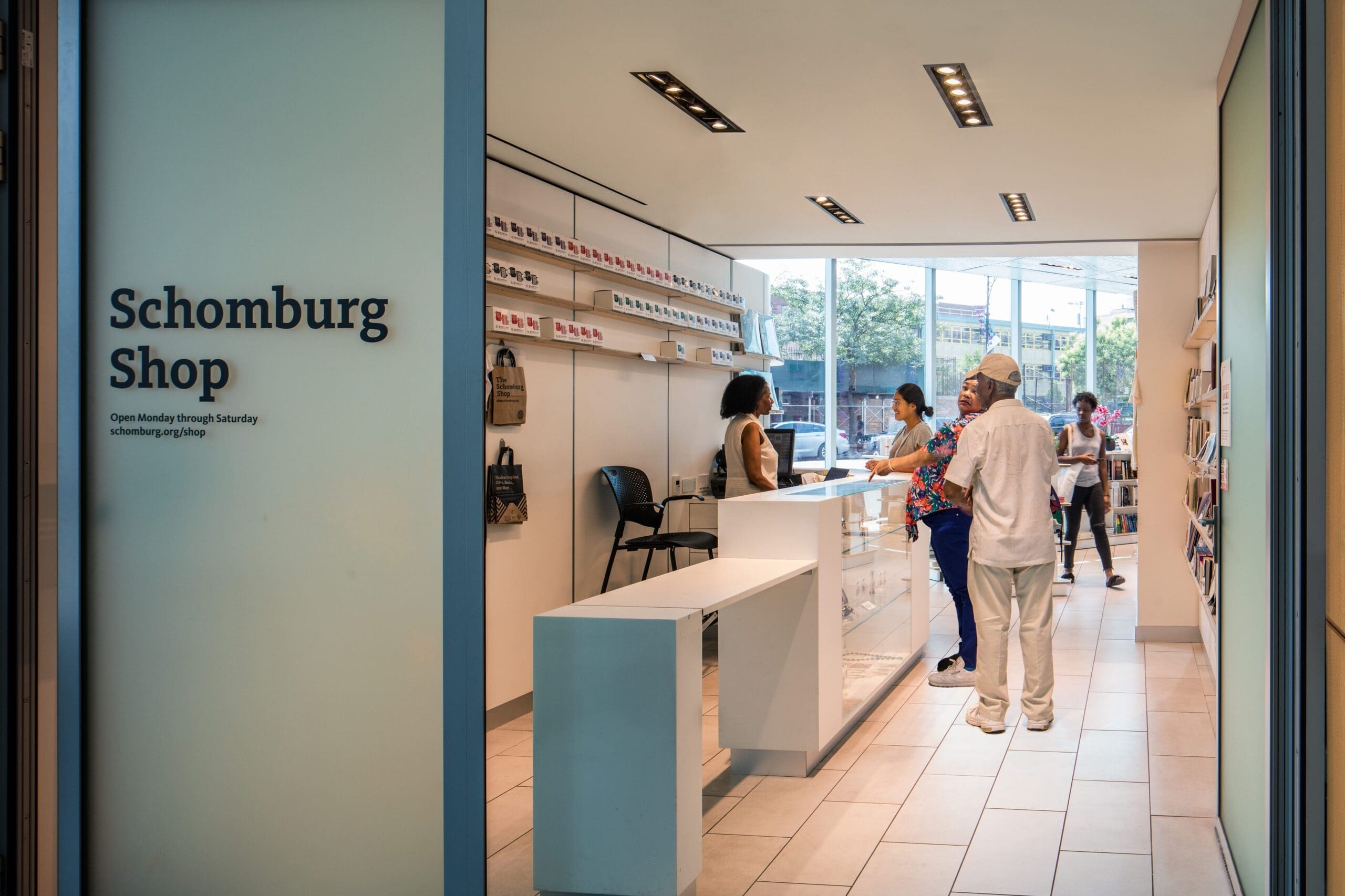
The Schomburg Shop
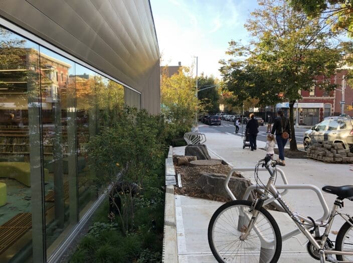
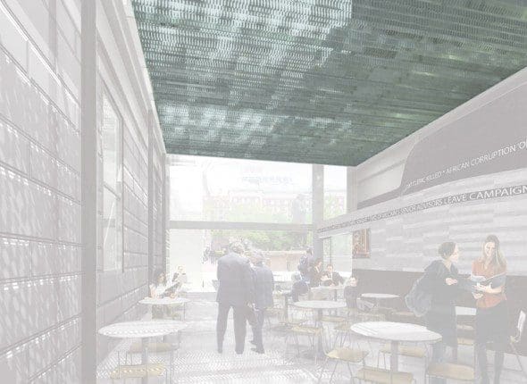
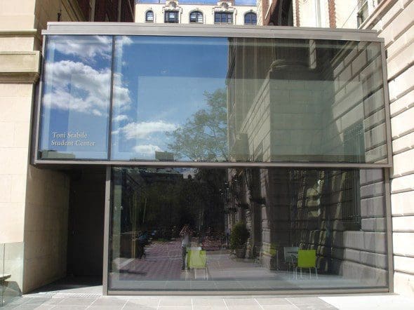
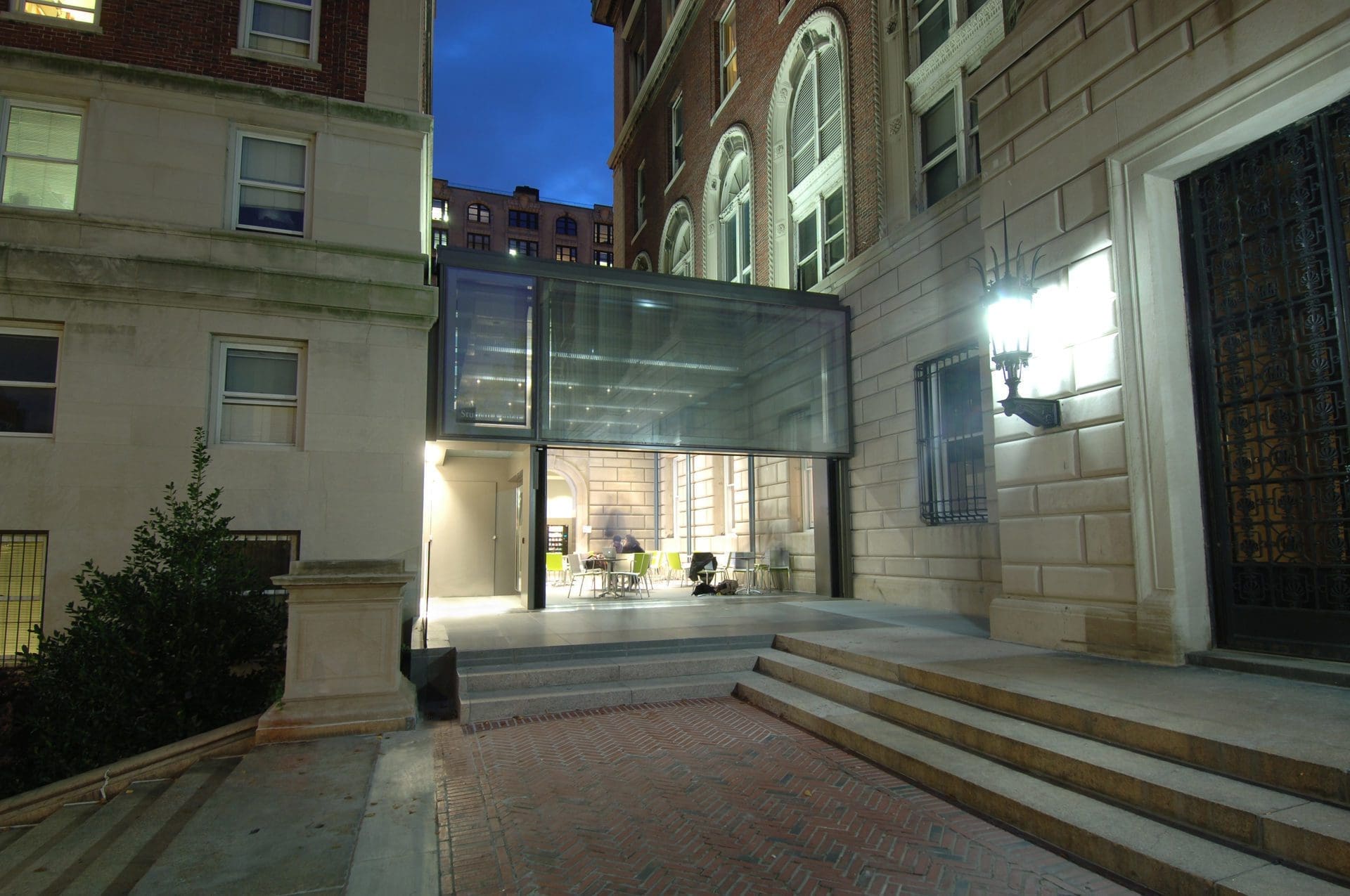
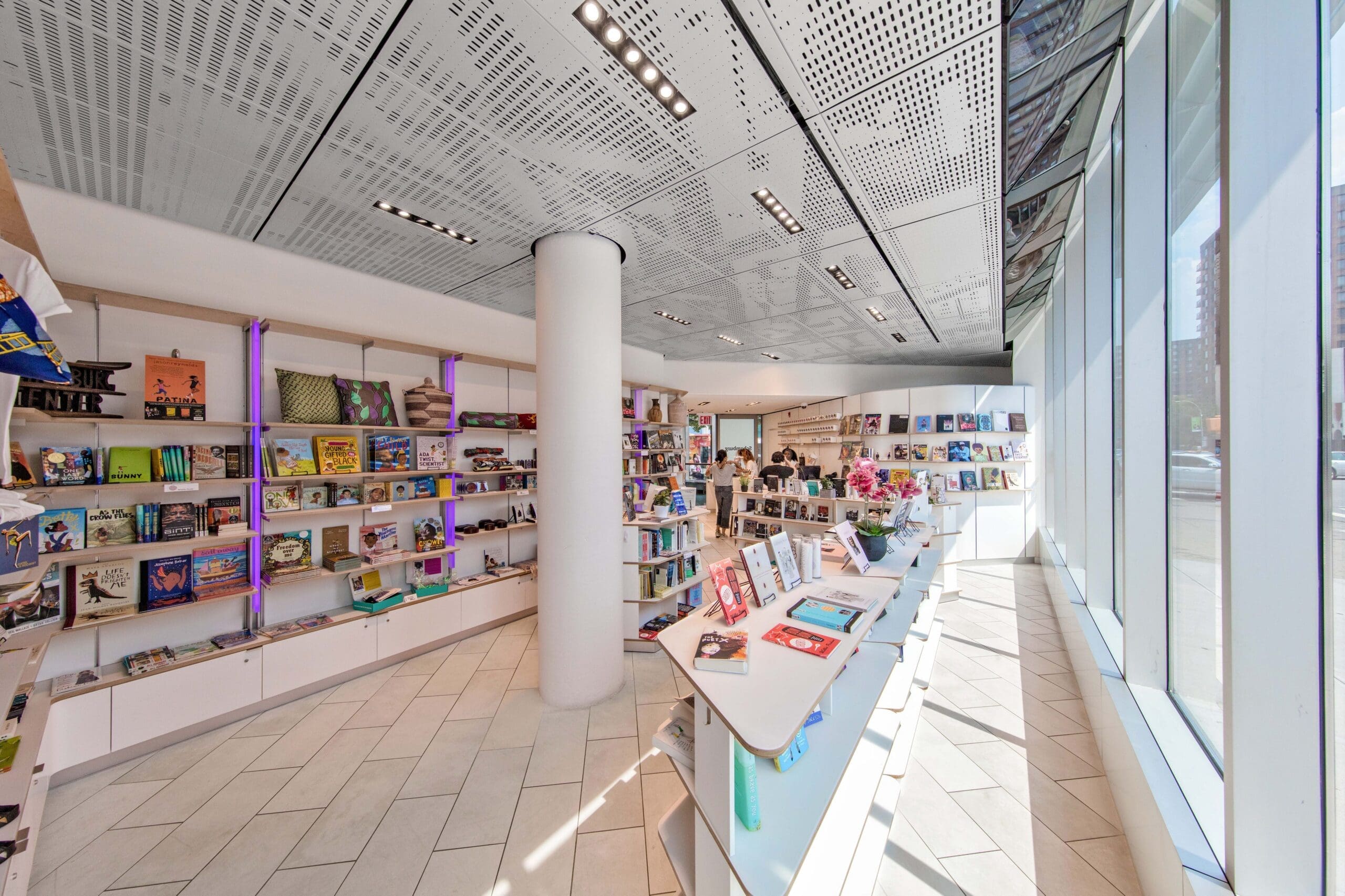
Another means of engaging the neighborhood with Schomburg’s culture was through the addition of the gift shop along 135th Street, which infills what was once a narrow exterior space. The shop sells eye-catching, clothing, jewelry, and books created by Black and Brown artists. Pedestrians on the sidewalk have a full view of these objects through a glazed wall—another invitation to engage with the center.
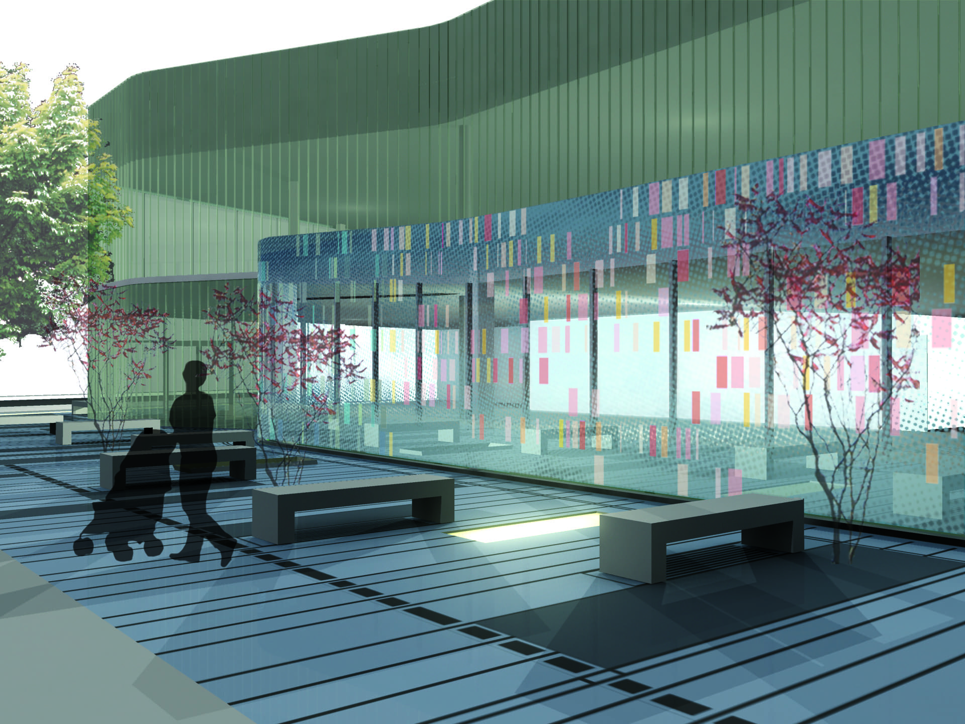
Interior and Exterior Connections
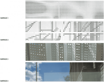
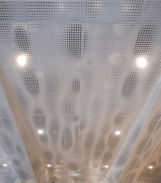
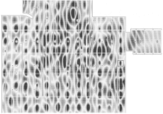
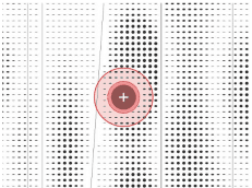
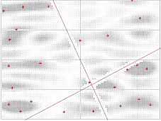
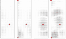
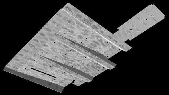
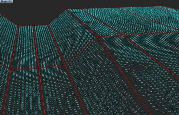
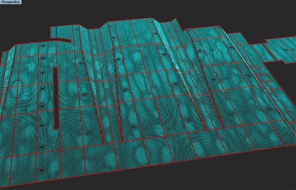
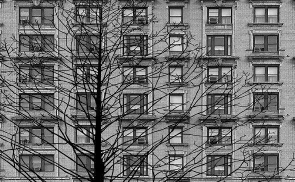
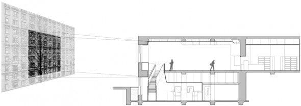
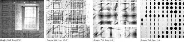
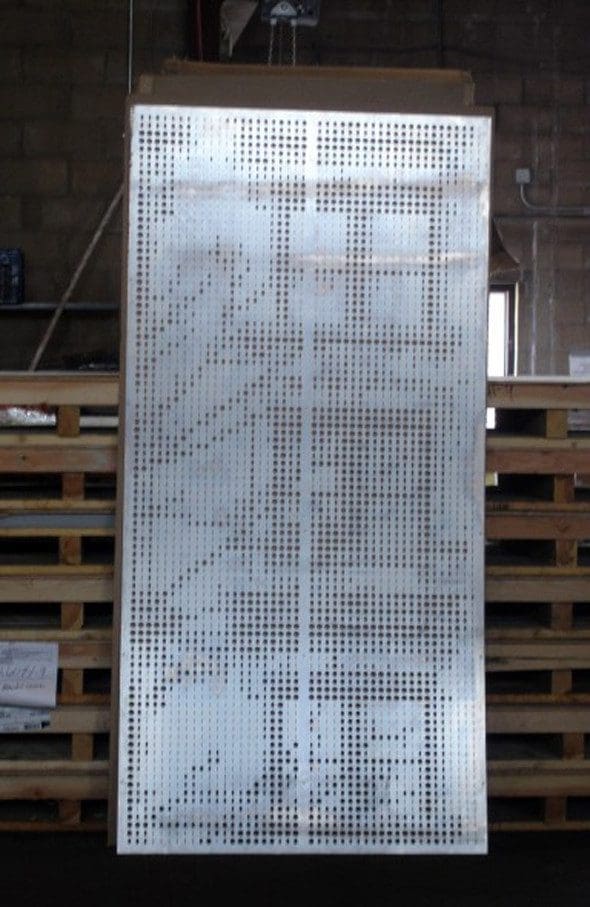
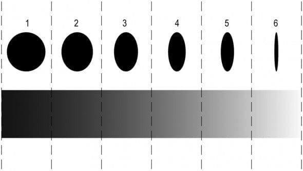
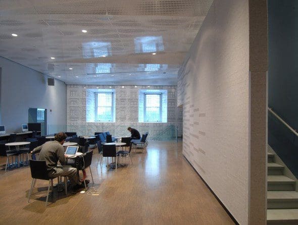
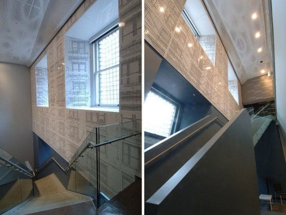
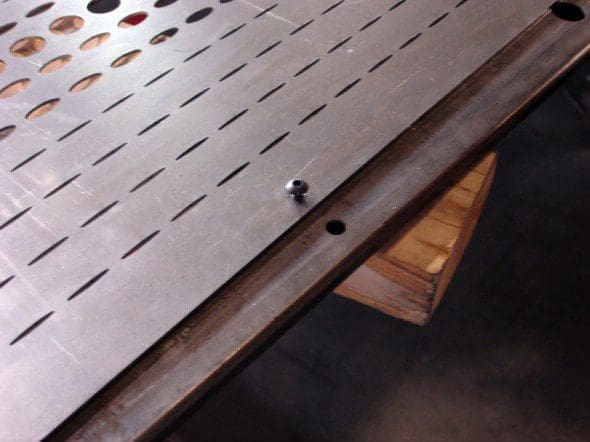
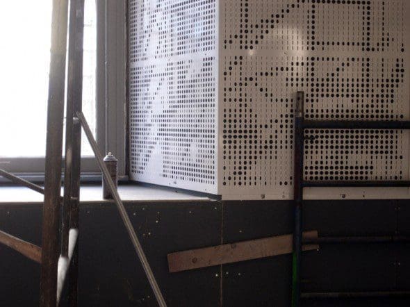
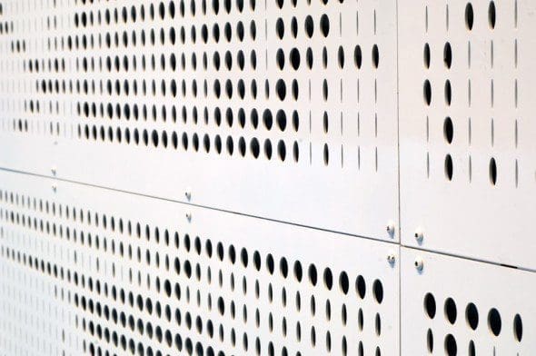
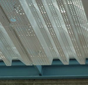
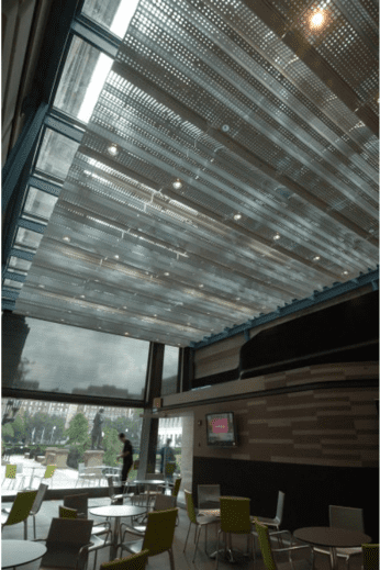
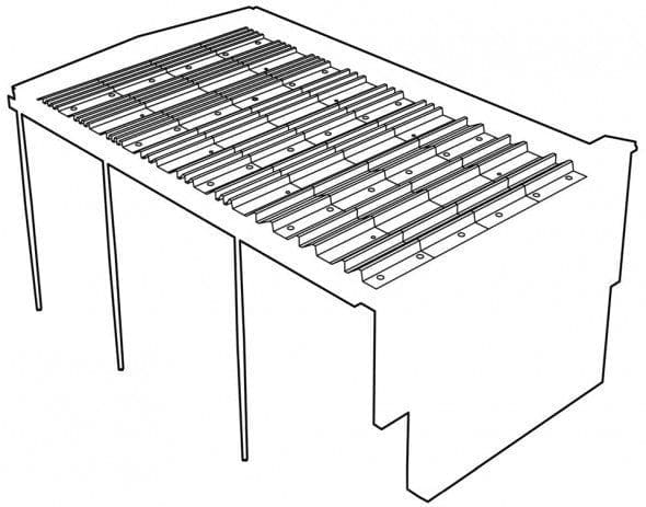
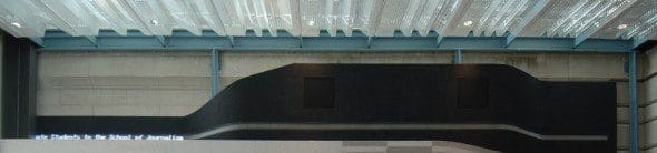
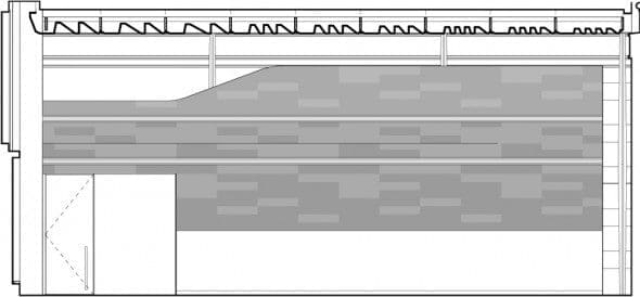
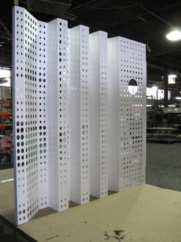
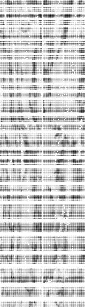
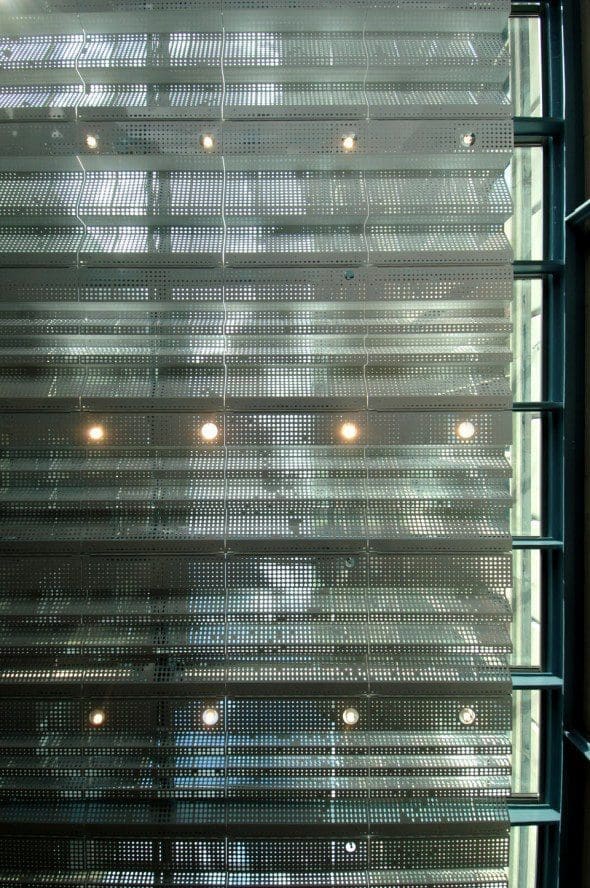
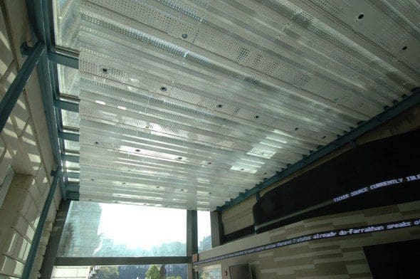
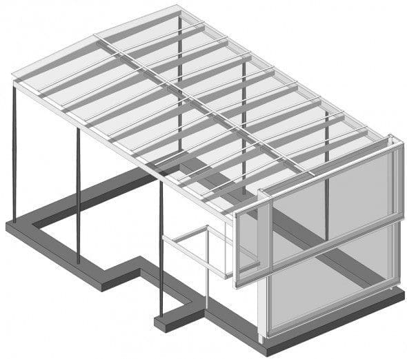
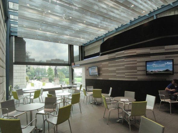
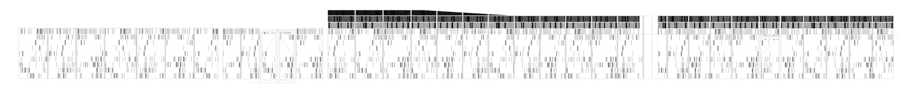
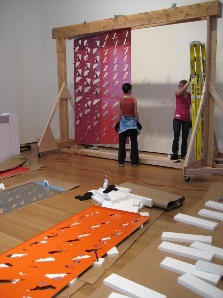
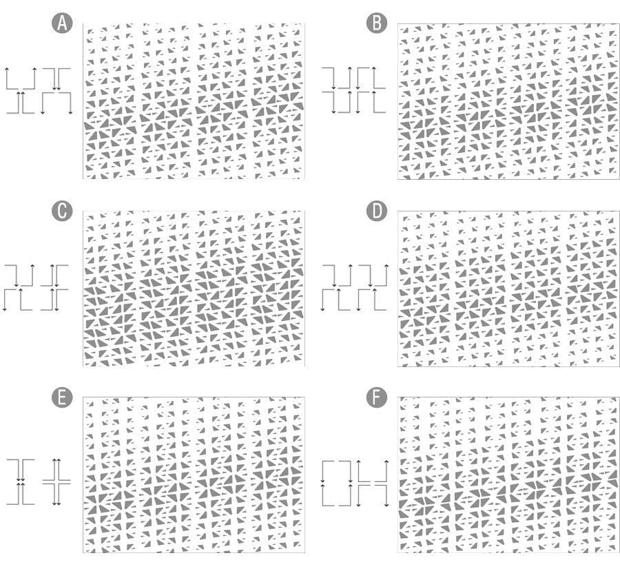
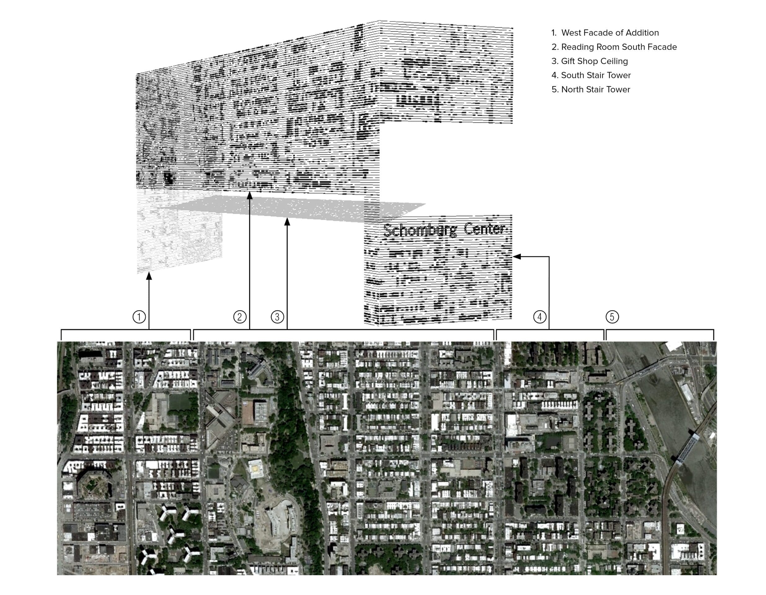
We tied south and east facades together by wrapping them in a perforated metal screen, into which a large digital display screen is recessed. The graphic pattern on the metal screen and in the gift shop’s glass frit pattern is a rasterized aerial view of the surrounding Harlem neighborhood. The same perforated metal screen also continues along the shop’s ceiling, where it serves as a floating platform for street-facing display monitors.
Sparking Interest
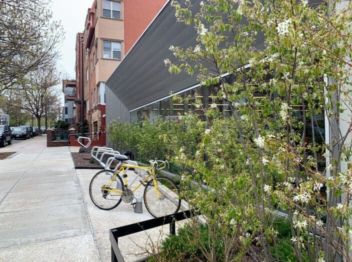
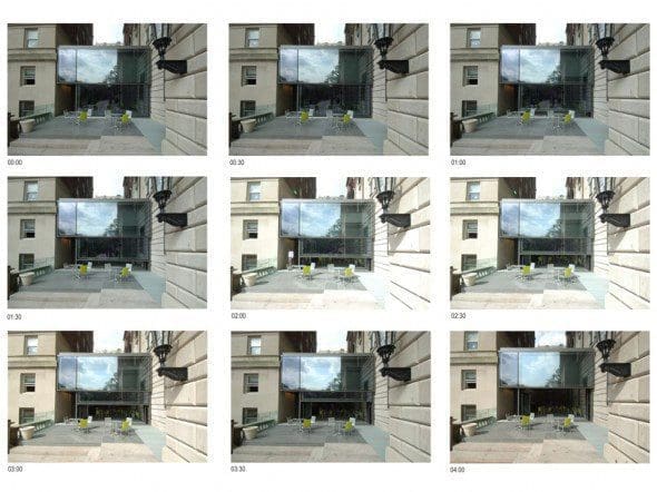
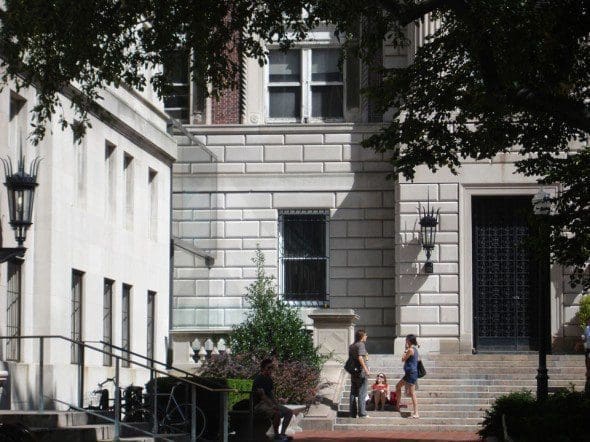
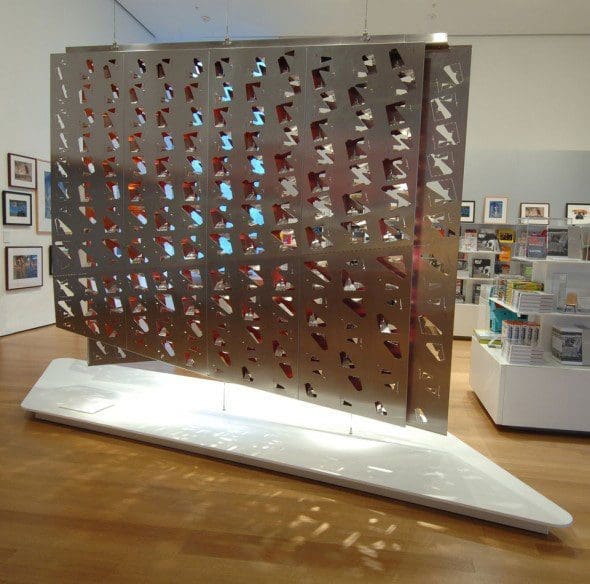
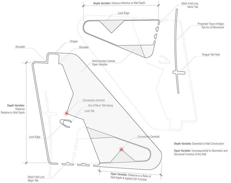
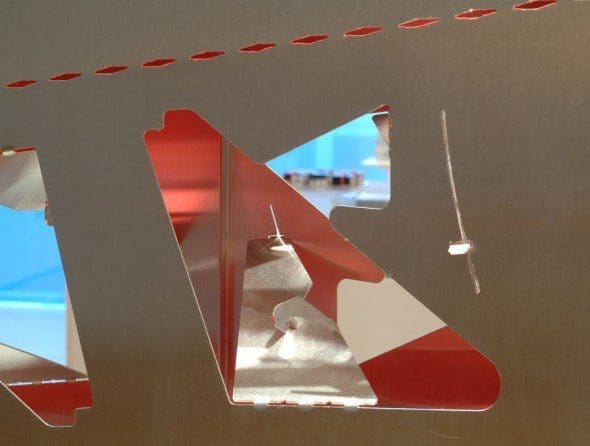
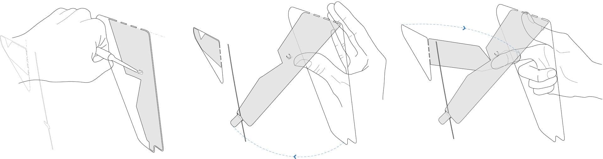
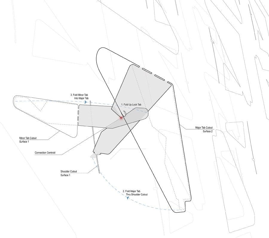
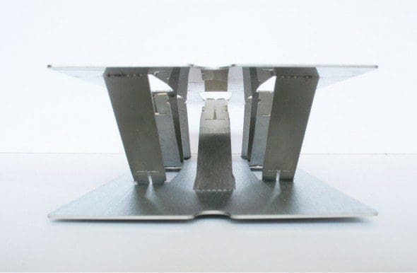
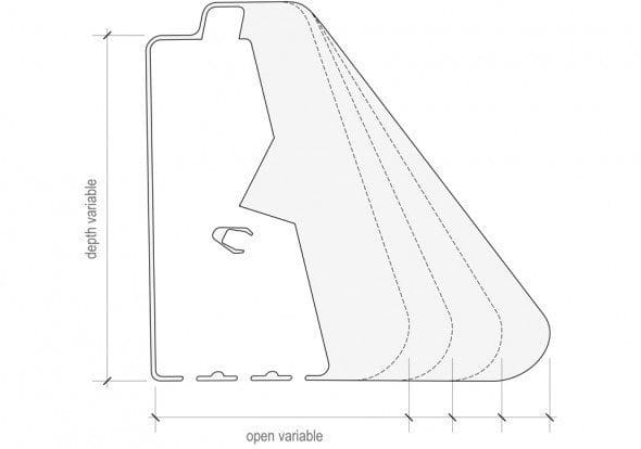
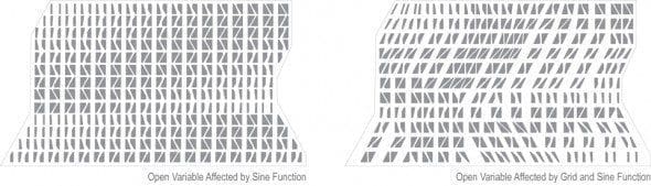
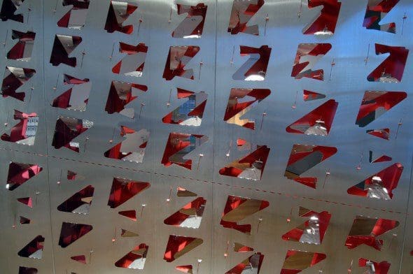
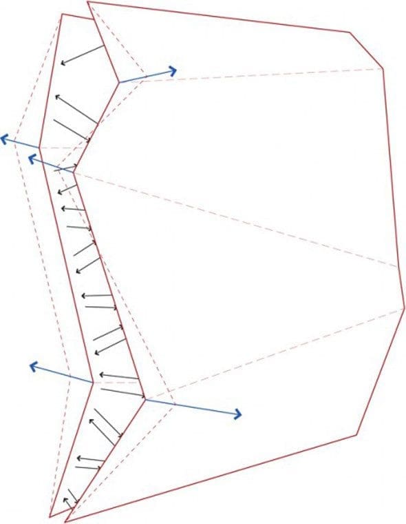
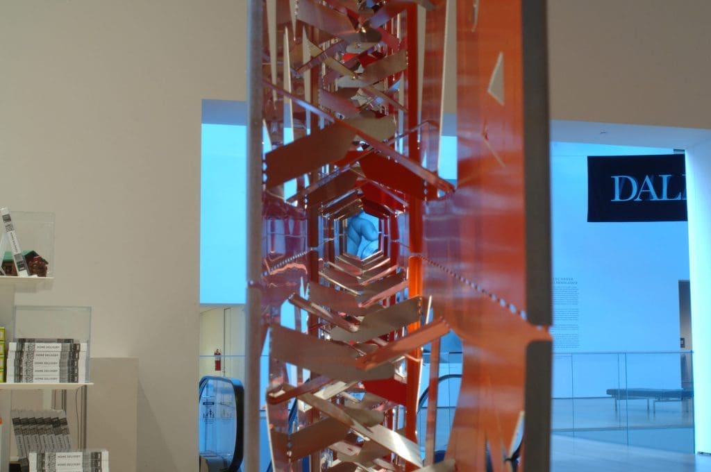
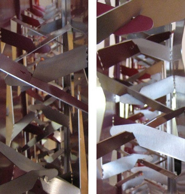
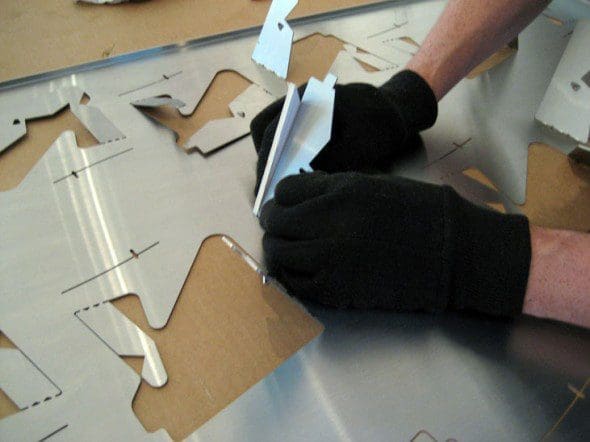
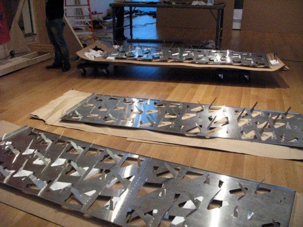
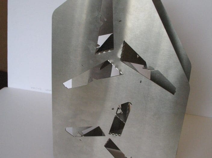
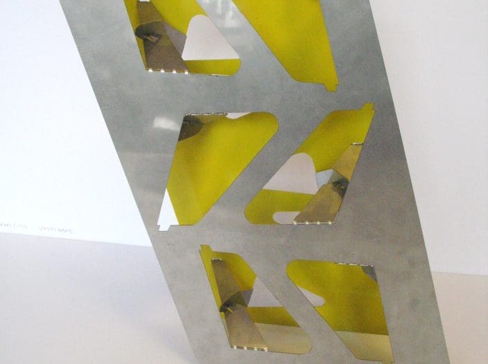
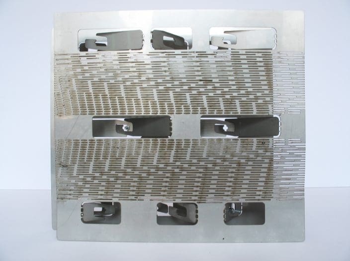
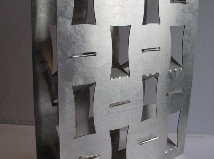
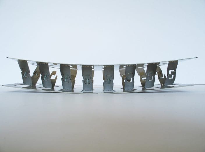
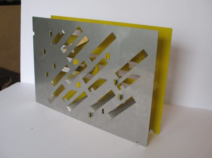
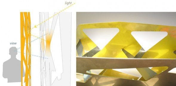
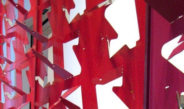
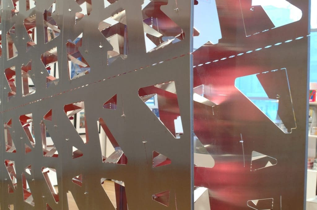
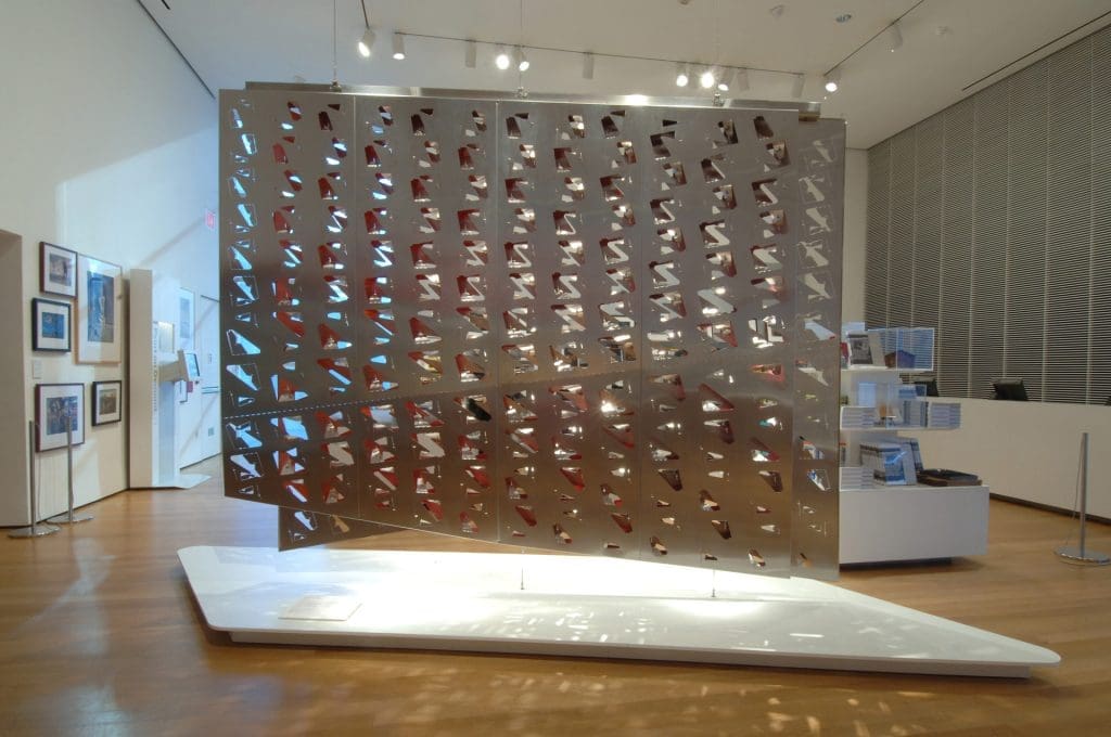
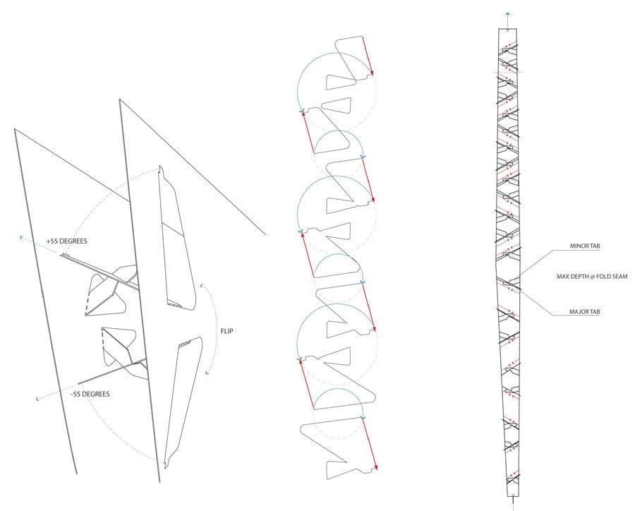
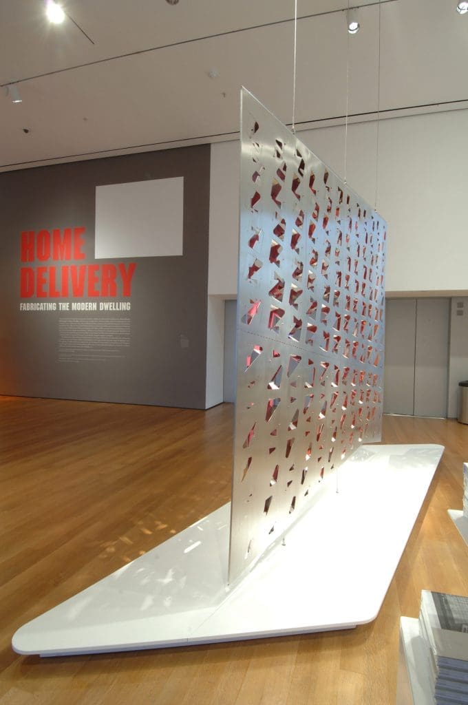
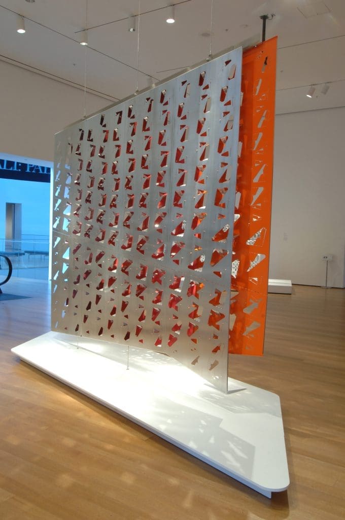
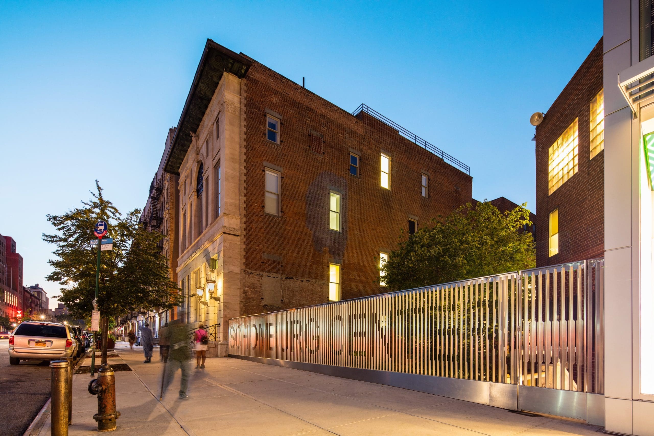
Along 135th Street, between the new gift shop and the McKim, Meade & White building, we designed a lenticular stainless steel fence to replace a masonry wall. When viewed from the east, notches in the bent steel plates spell out “Schomburg Center.” Viewed from the opposite direction, the fence reads “Center for Research in Black Culture.” The new fence offers transparency into the garden beyond, while standing as a playful, dynamic sign that changes appearance with light conditions and piques visitor interest.
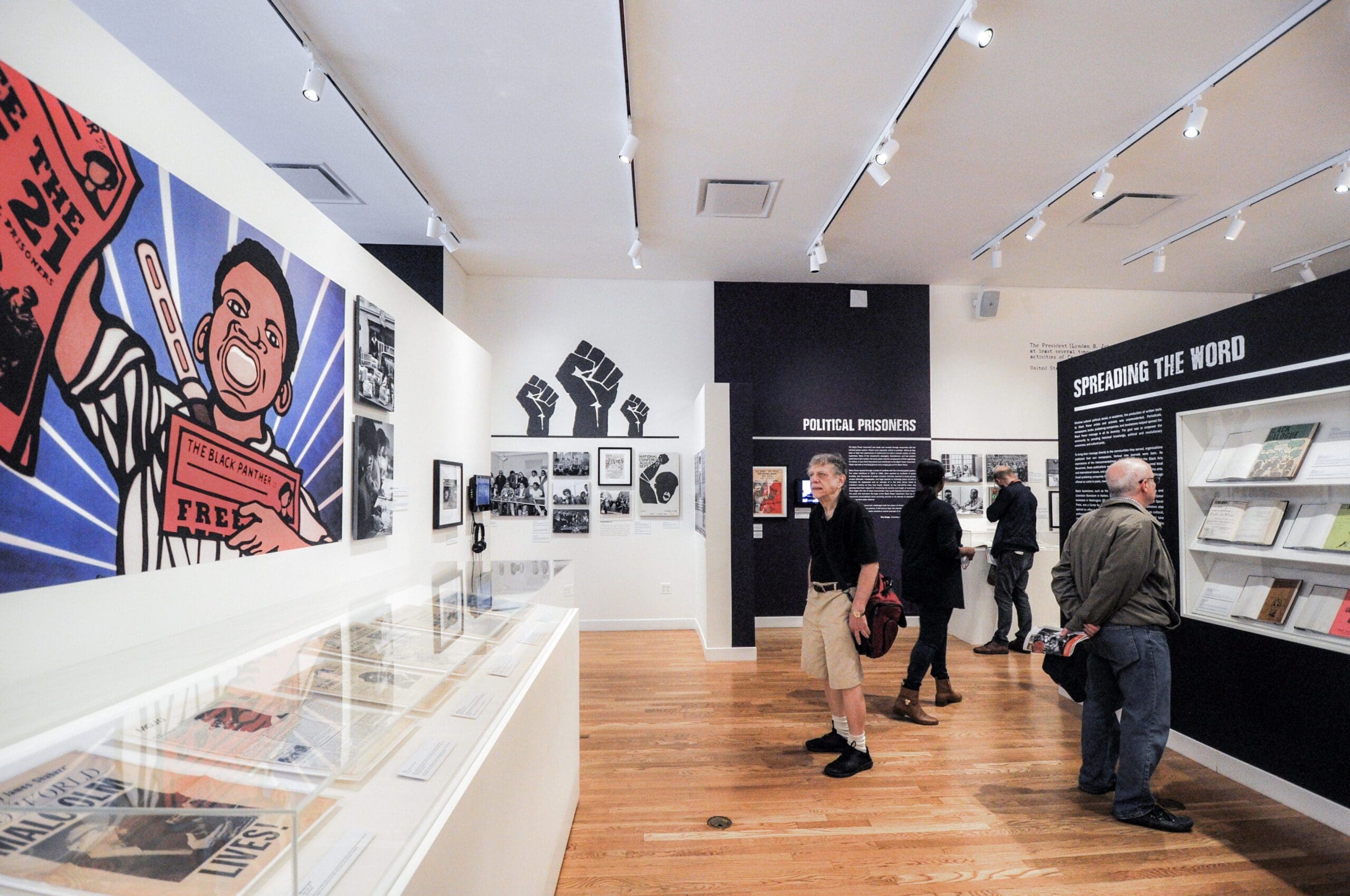
Creating an Engaging Experience for All Visitors
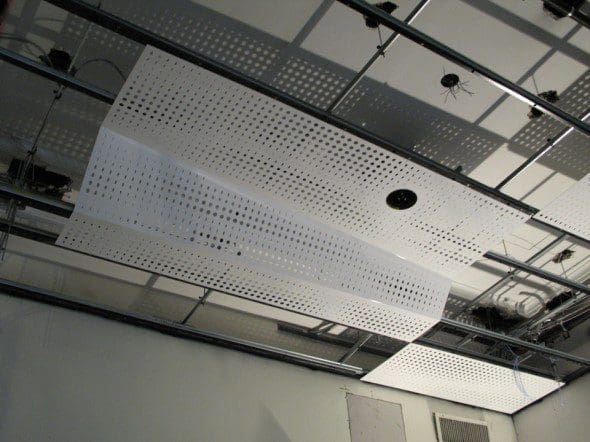
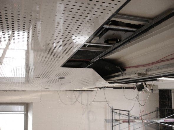
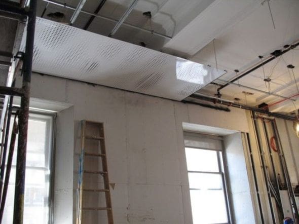
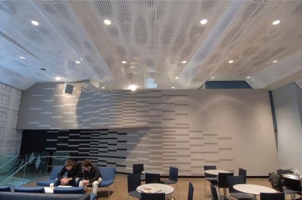
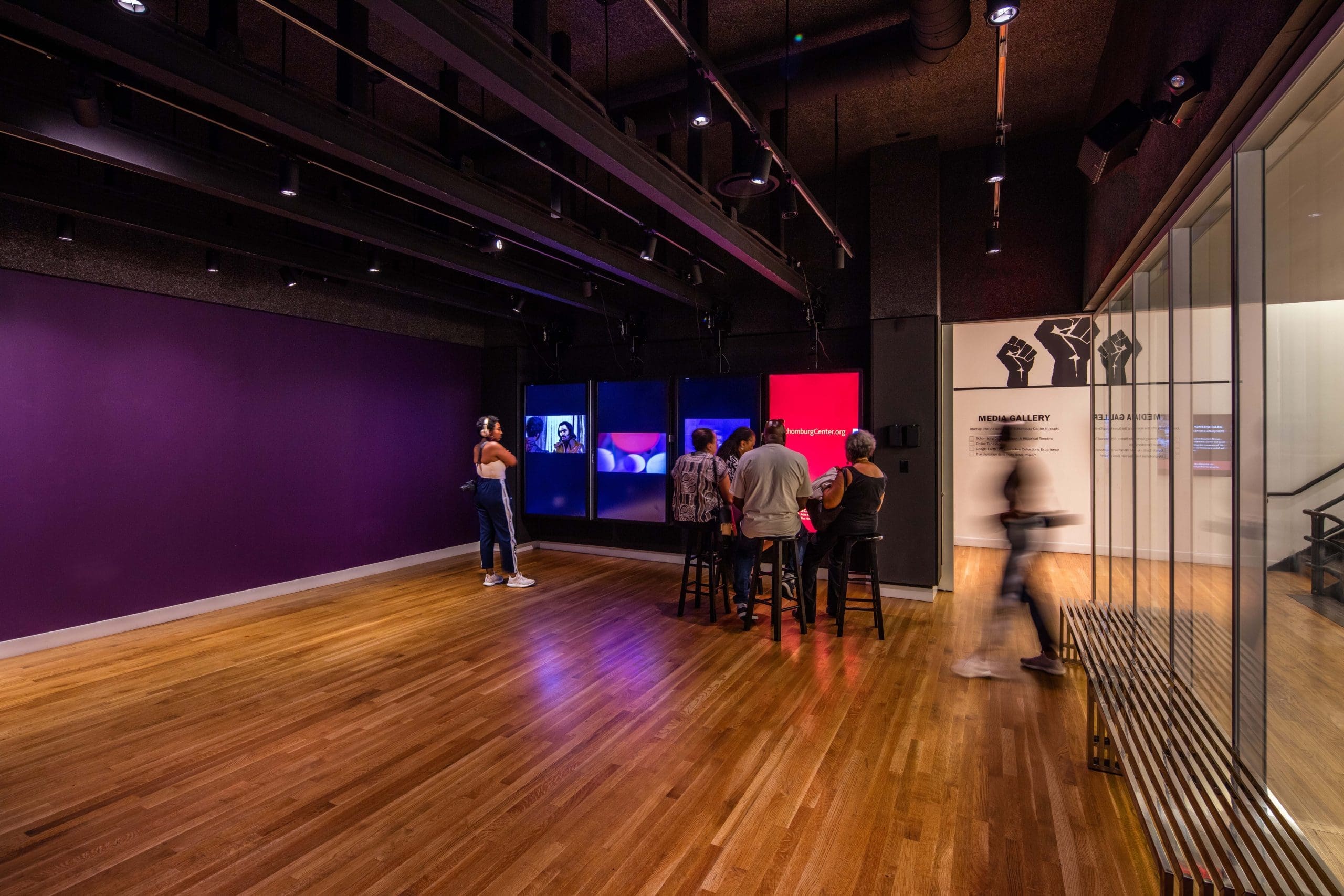
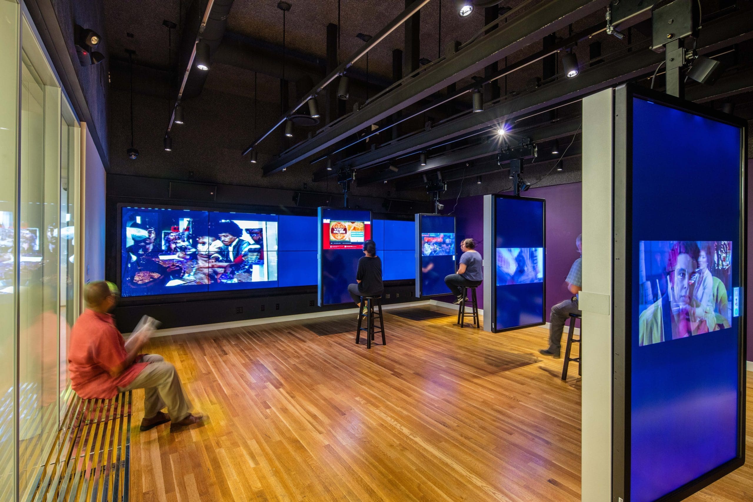
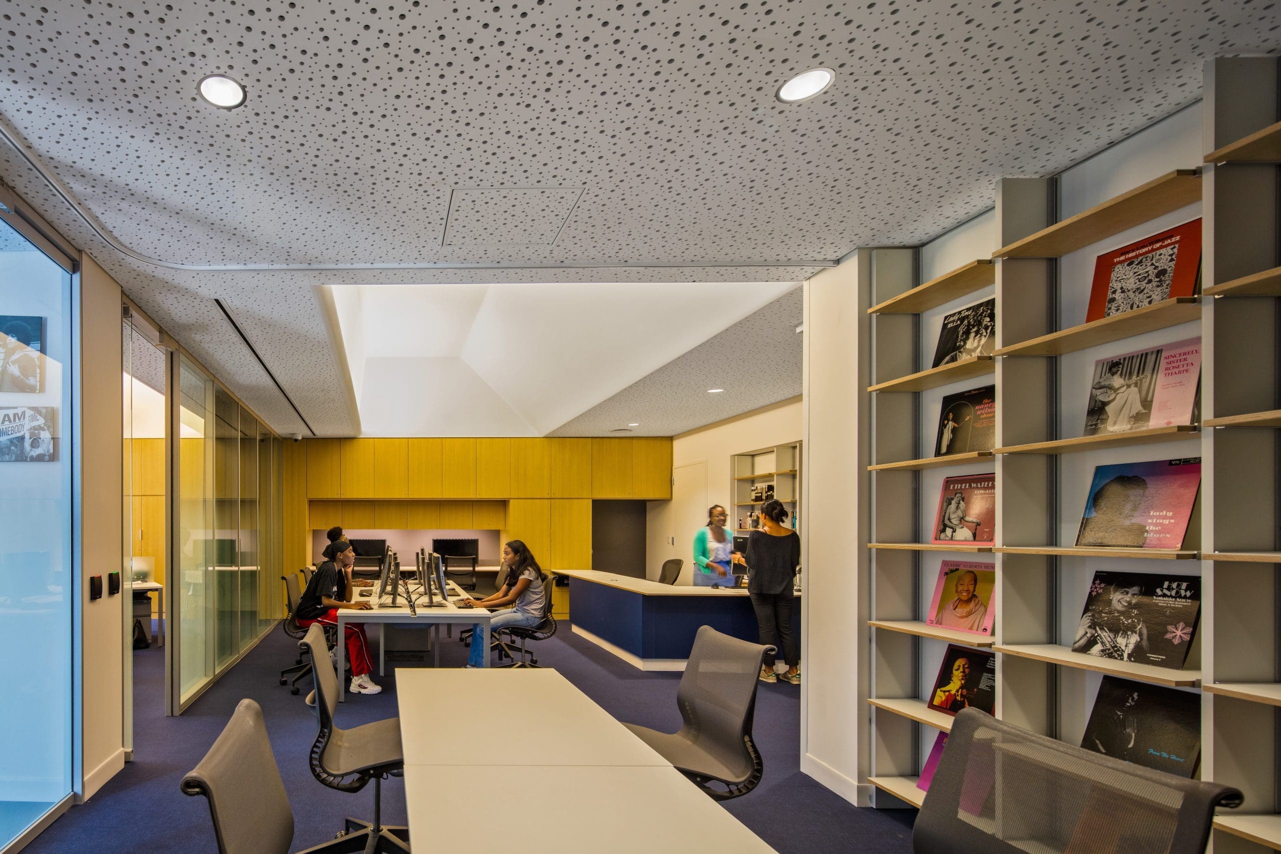
At the interior of the original Schomburg building—the 1905 McKim, Meade & White library—we created two gallery spaces that further advance the concept of “bringing the collection to the street.” These spaces house exhibitions that are open to the public. They are dedicated spaces for displaying collections to a public whose interests may lay outside of typical researcher’s. One of these, the Youth Media Gallery, hosts easily programmable interactive digital displays that slide and pivot along the ceiling, allowing for quick customization of a gallery space intended to increase the center’s engagement with young people.
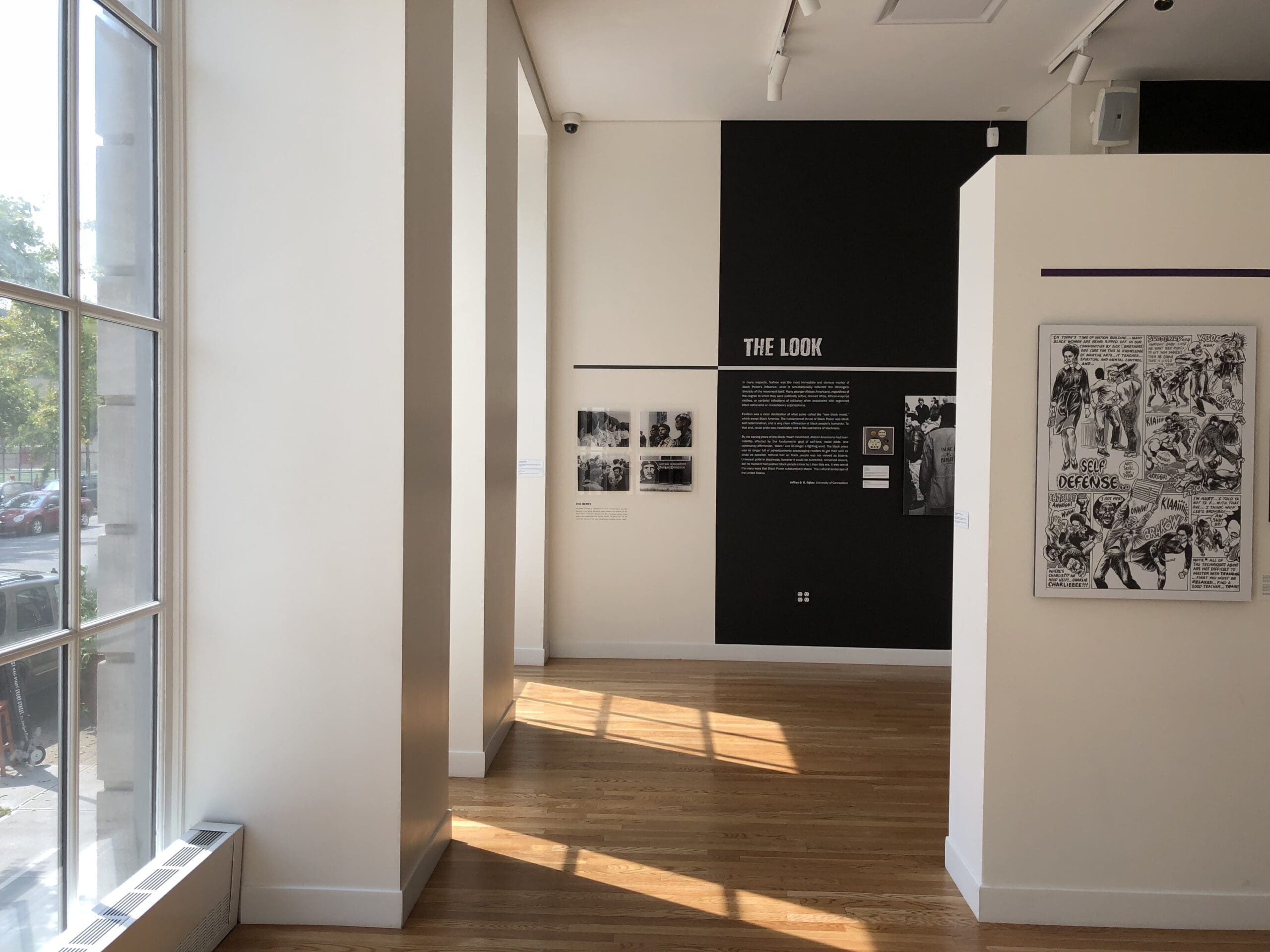
Showcasing Collections
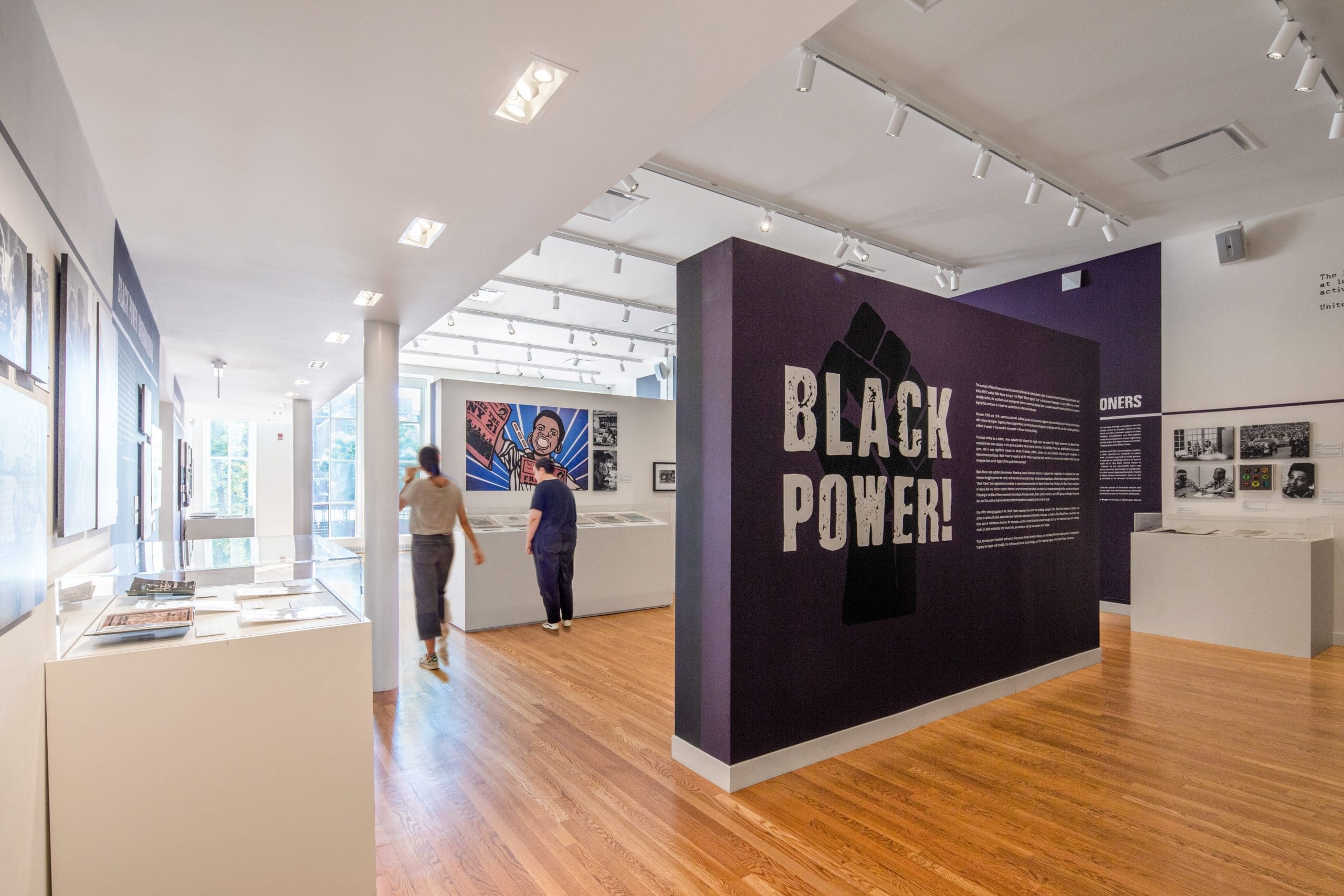
Adjacent to the Youth Media Gallery, the Main Gallery offers a light filled space for displaying Schomburg’s own collection as well as visiting exhibitions.
Better Access to the Collection
The Schomburg Center has long been one of the leading and most visited institutions for researchers studying African American, African Diaspora, and African experiences. Our project improved and updated research spaces, reading rooms, and archival storage to provide state of the art facilities for researchers and staff members. By addressing the specific needs of the center’s different research divisions, we created spaces that facilitate viewing, studying, and handling the collections. These include: the Reading Room for the Manuscripts, Archives and Rare Books Division; the Reading Room for the Moving Image and Recorded Sound Division; and the Archive Room for the Rare Books, in addition to other work area and collection storage spaces.
Re-Envisioning Research Space
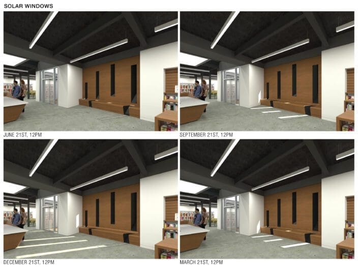
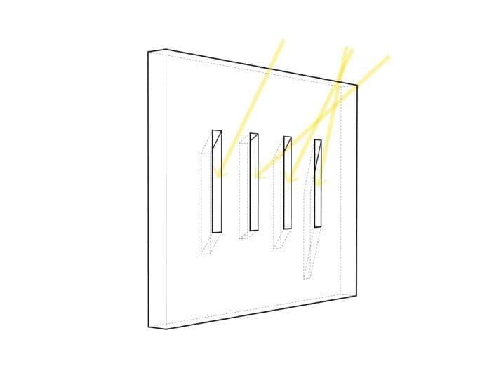
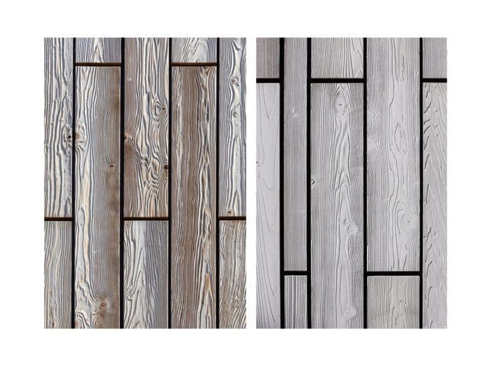
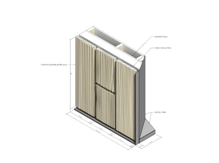
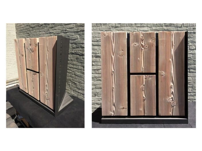
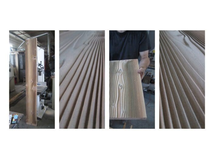
Marble Fairbanks fully renovated the The Manuscripts Division Reading Room, which occupies an open, octagonal room that was part of J. Max Bond’s original 1980 design. Acoustic wood paneling brings warmth to the space while also moderating natural light.
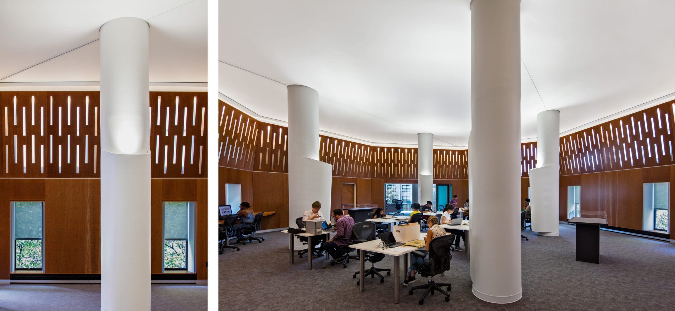
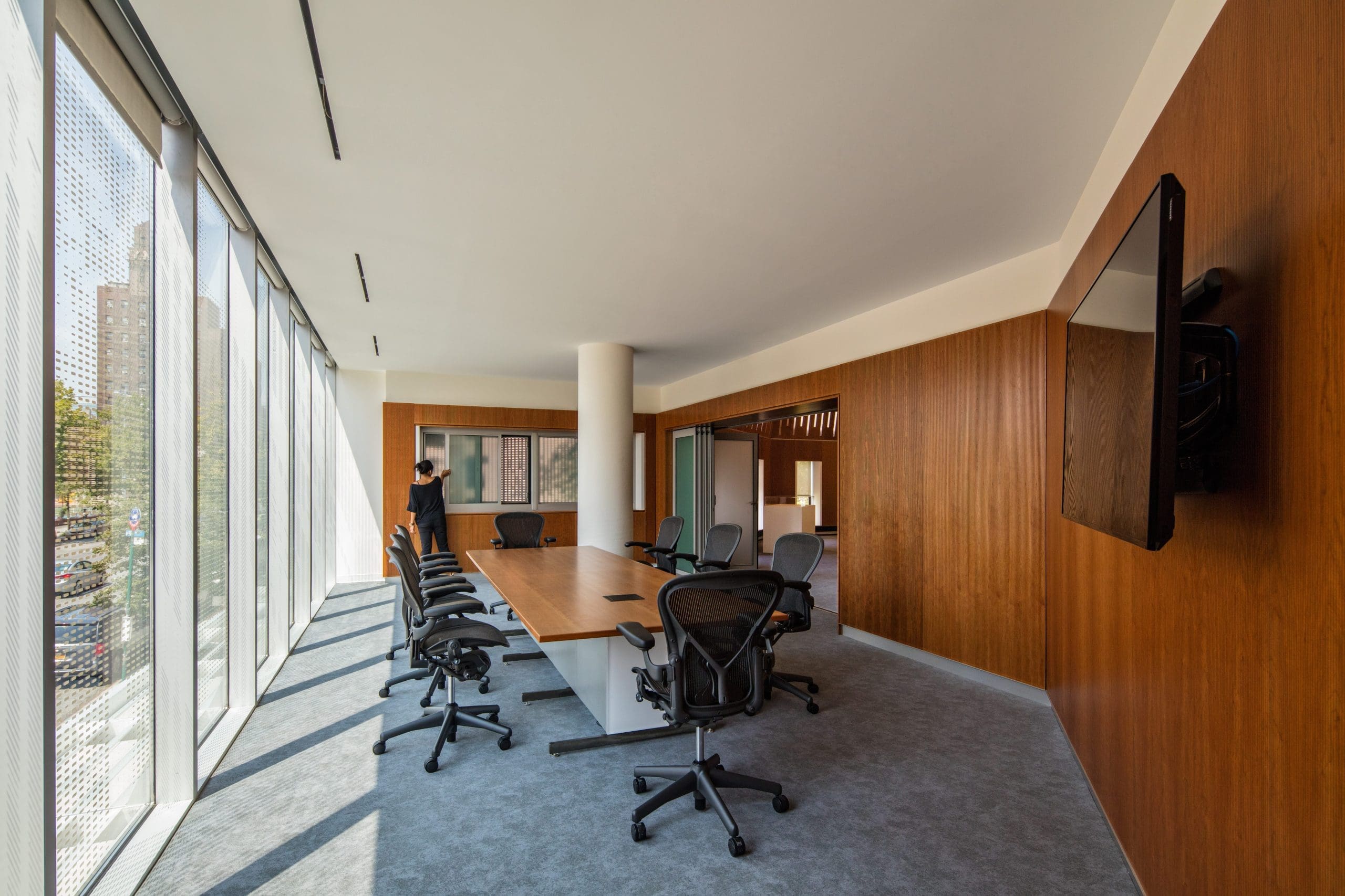
Meeting Space Connected to the Community
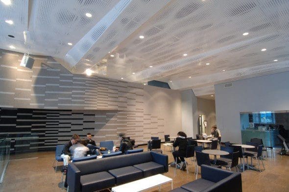
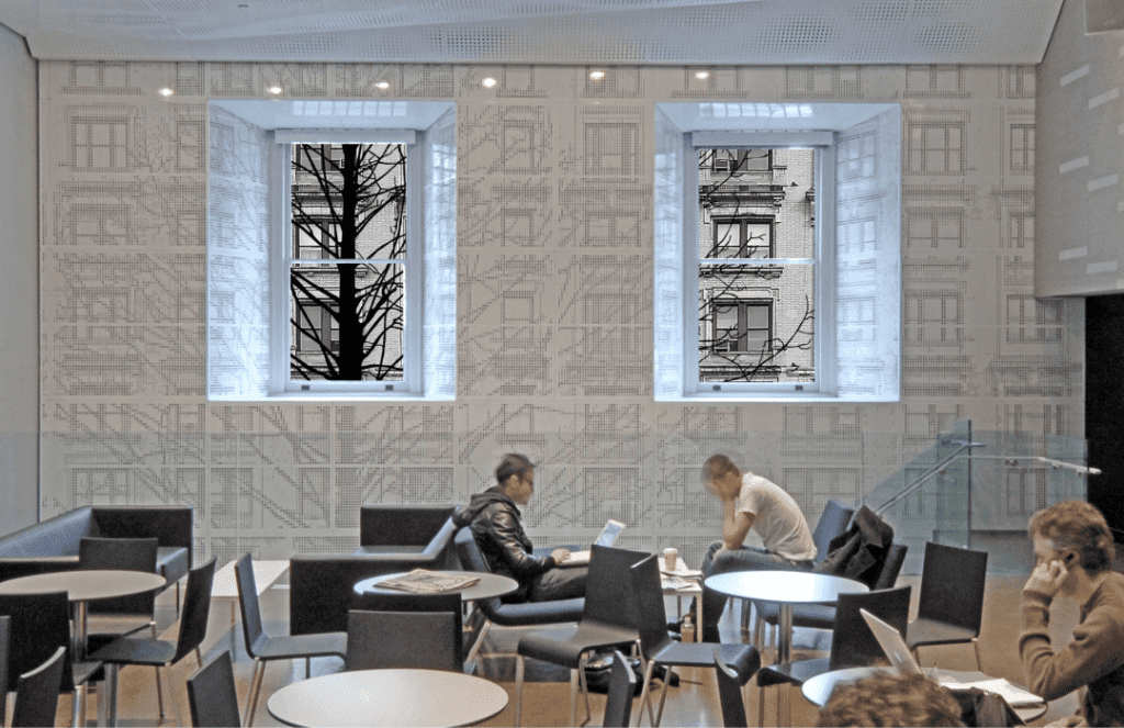
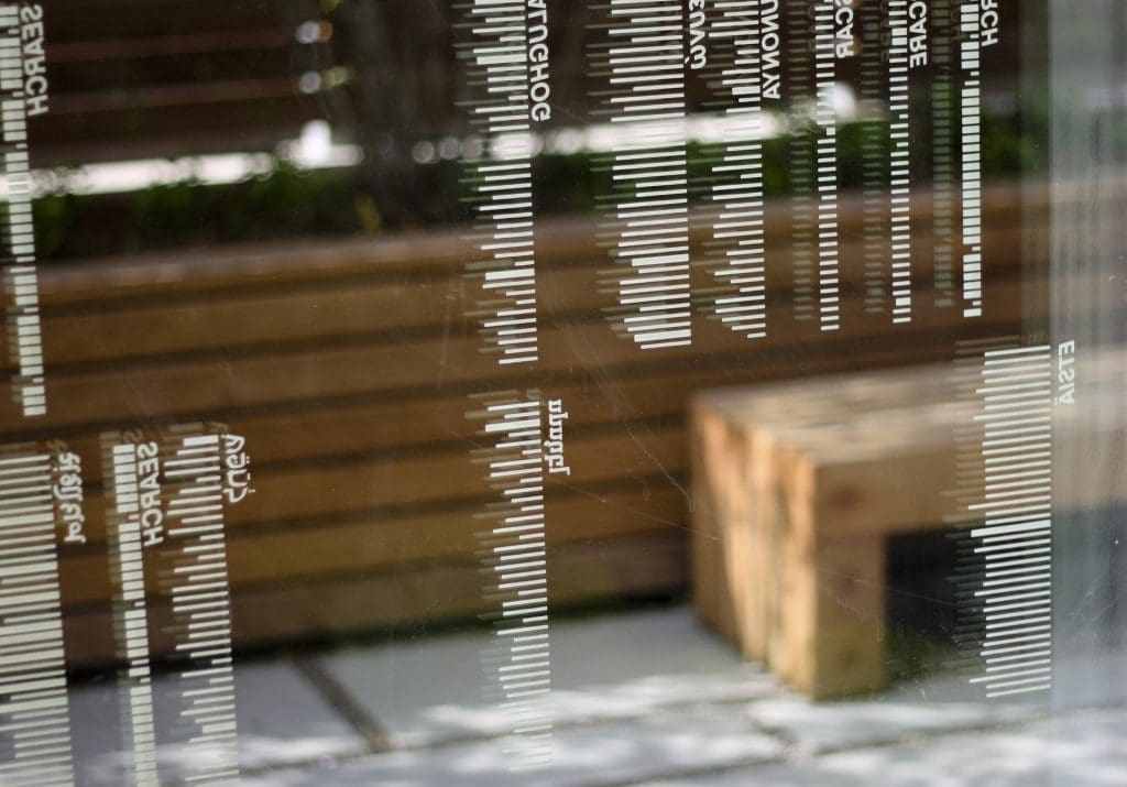
Located directly above the gift shop and part of the added infill volume along 135 Street, the Conference Room offers Schomburg’s community a place to meet that feels fully immersed in its neighborhood, thanks to the full height windows, which feature a frit pattern of a rasterized aerial photo of Harlem. The room flanks the octagonal Reading Room and adopts its material palette to create a space that feels anchored to the collection it supports.
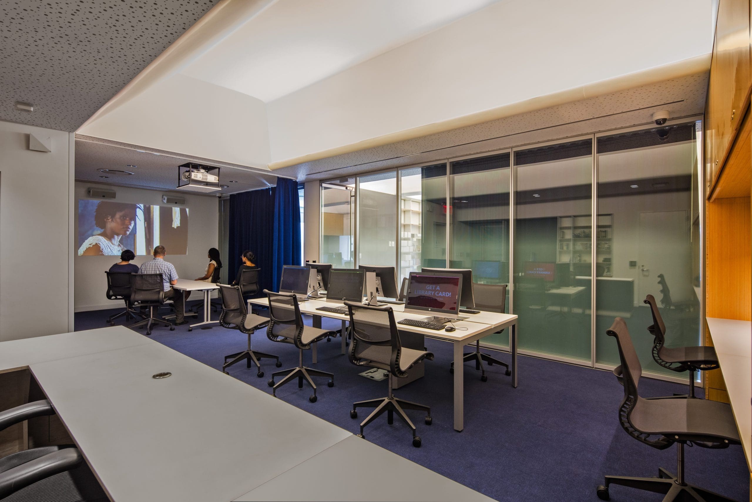
Multimedia Research Space
The Reading Room for Moving Image and Recorded Sound Division provides researchers a comfortable space in proximity to the collection it supports. Warm millwork, indigo color accents, varying ceiling textures, and an integrated display wall give the sense of being in a jewel box. The space features a screening room that can be partitioned off by a full height, heavy, curtain that evokes a traditional movie theater experience.
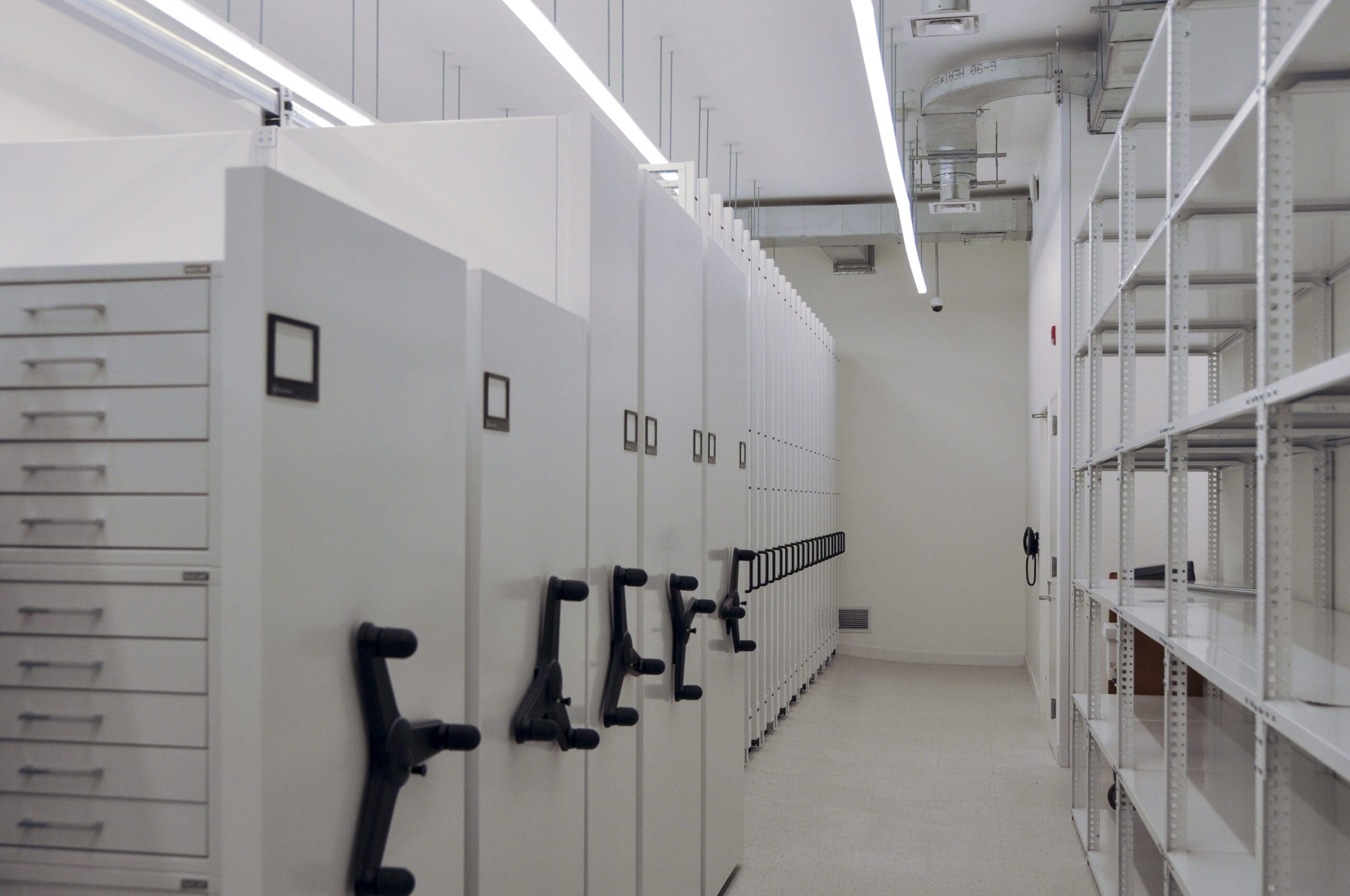
Upgraded Collections Storage
New collection storage and curatorial spaces use compact storage to safely store Schomburg’s more than 10 million artifacts.
Top: collections storage in the McKim, Meade & White building
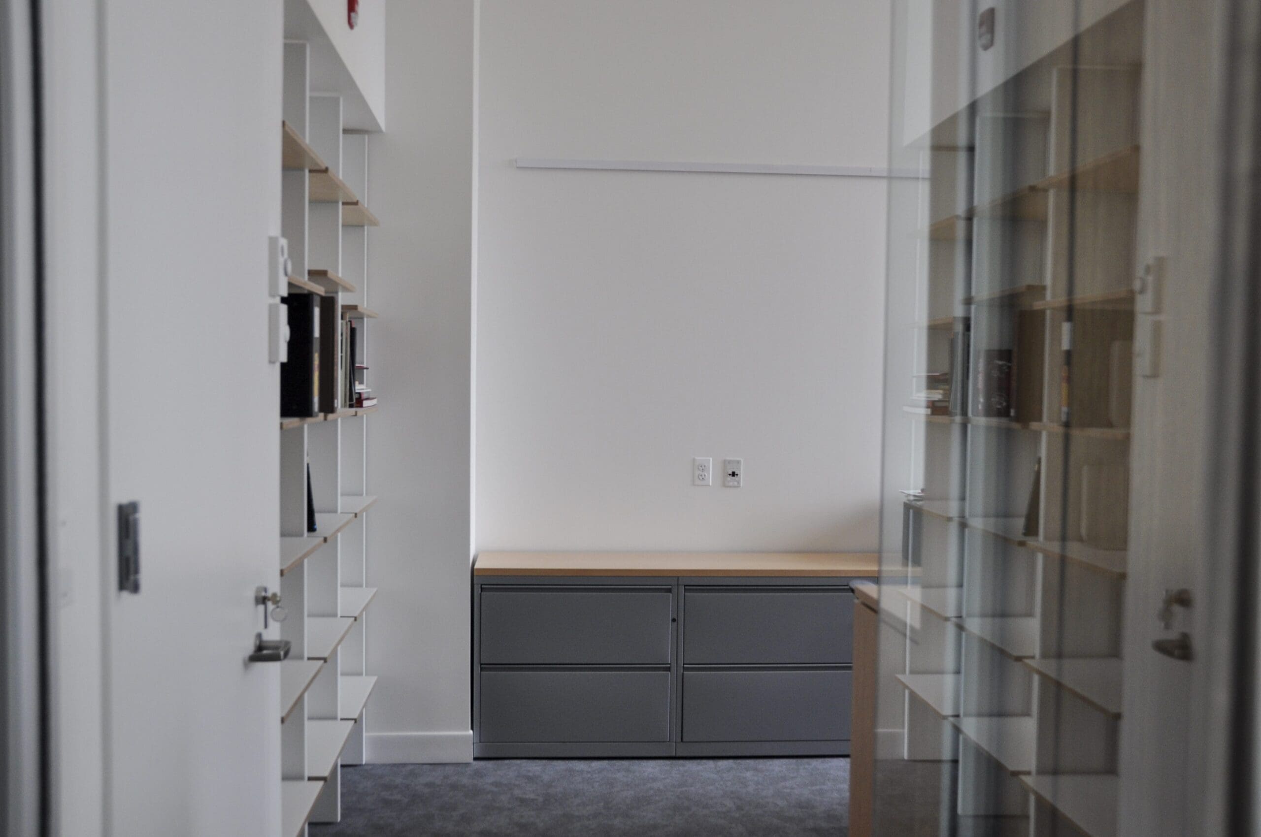
Bottom: the director’s office—also in the McKim, Meade & White building—within close proximity of collections
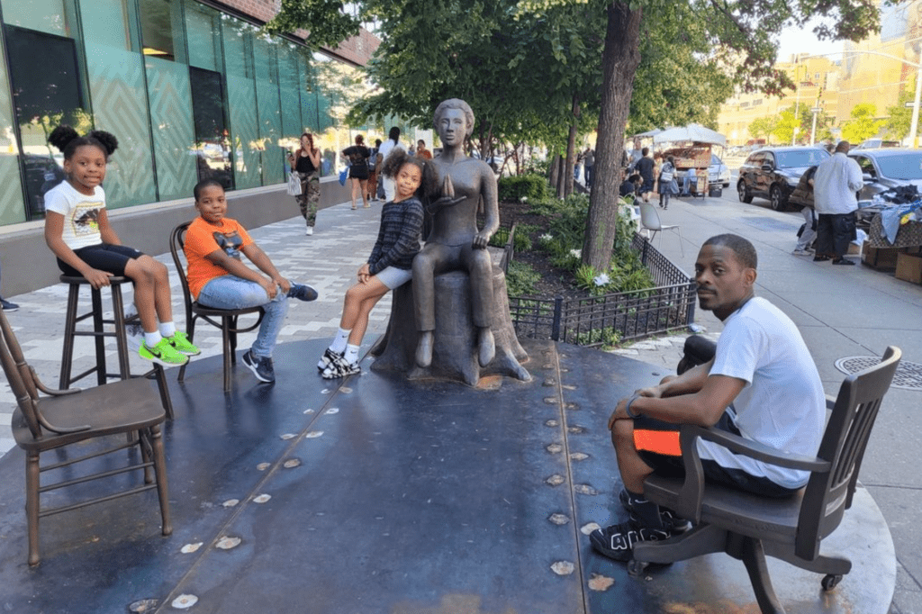
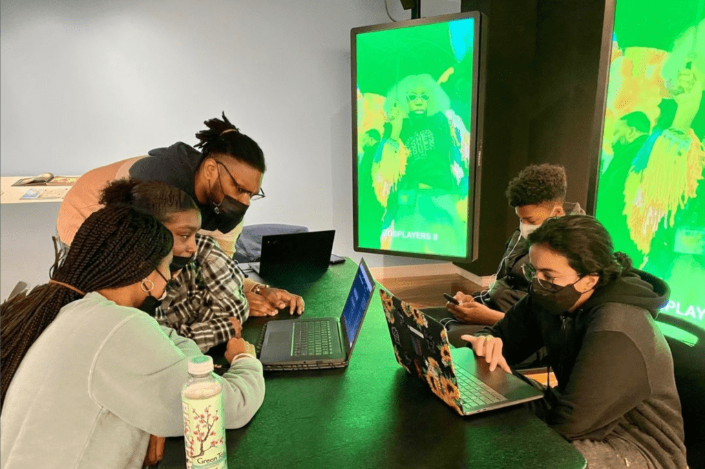
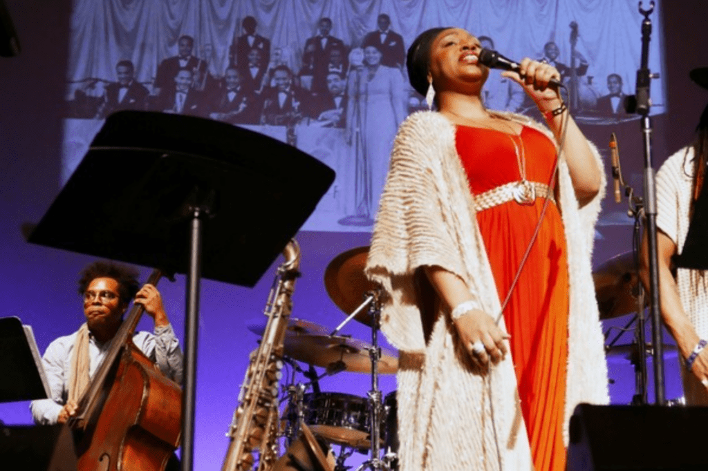
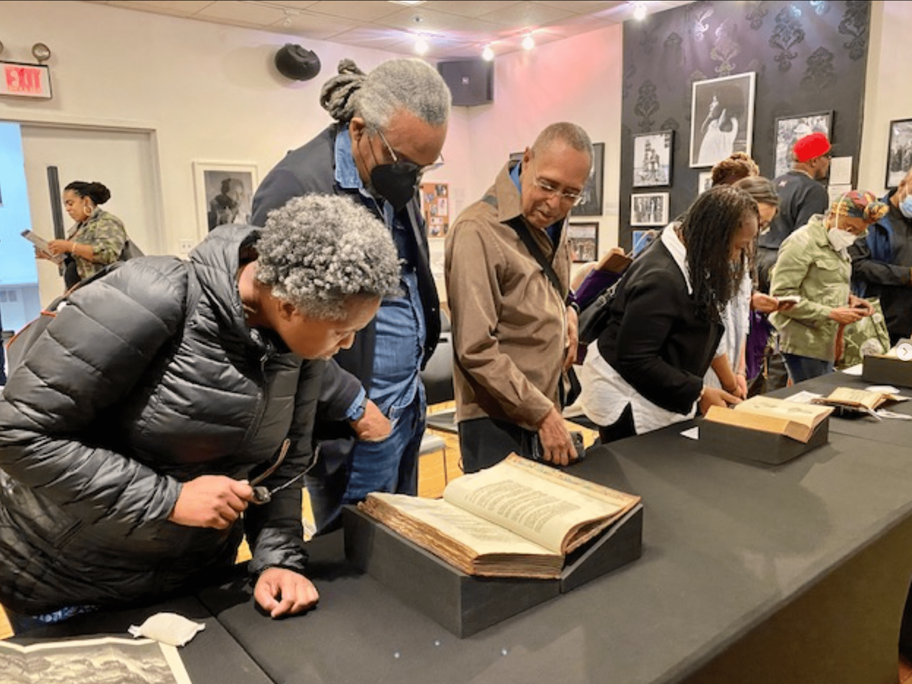
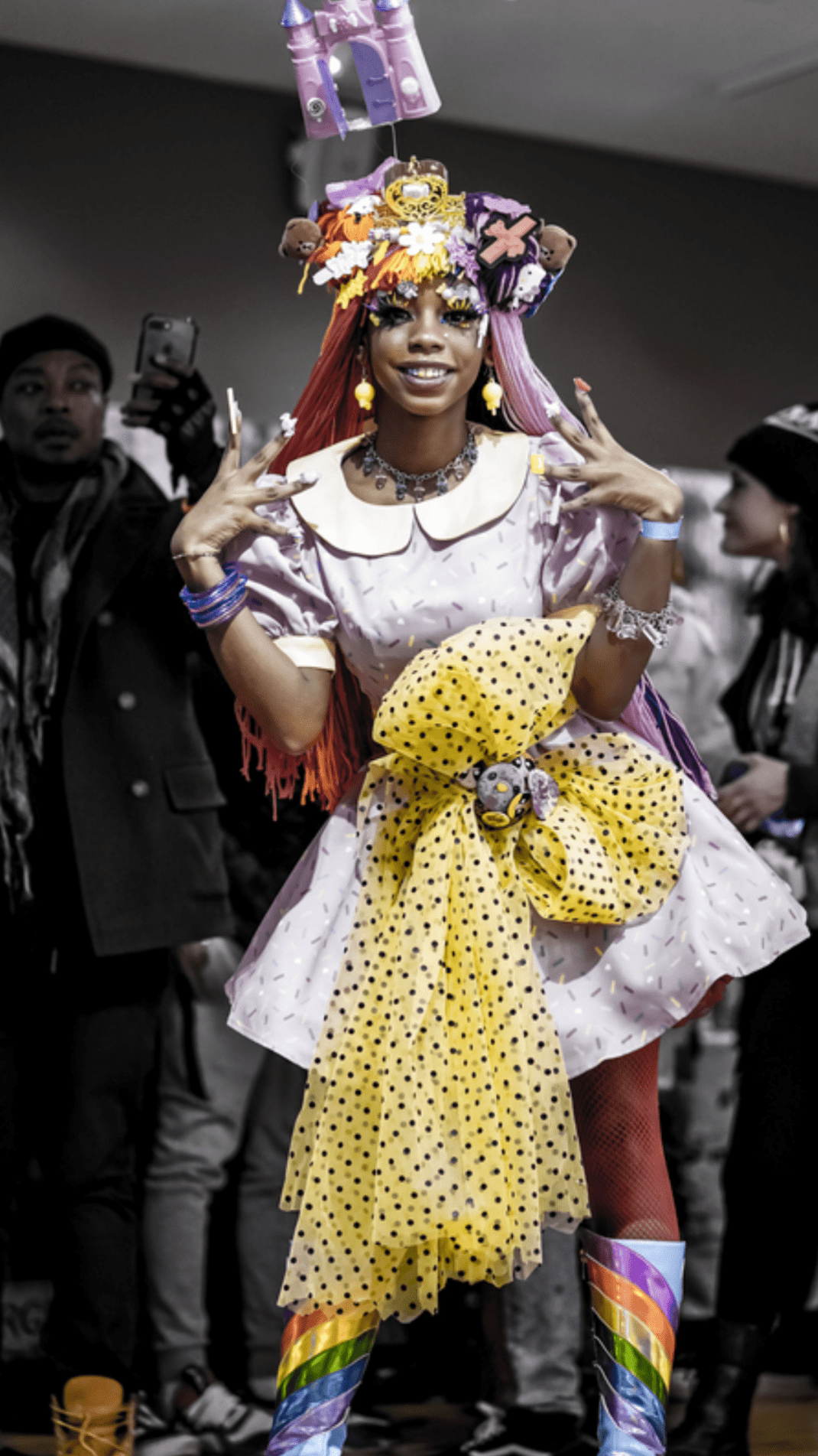
A Hub for Community and Culture
The Schomburg Center is one of New York Public Library’s research libraries. Researchers, scholars, and students from all over the world visit the building to study specific artifacts and documents that can only be found there. However, the building also brings together people of all ages and backgrounds to celebrate and enjoy dance, literature, music, history—all forms of black culture. The images below show events that the center has featured on its Instagram feed. One of these, the Schomburg Center Junior Scholars Program, exemplifies Schomburg’s dual mission as a space for both research and community engagement. The program accepts 100 students each year to attend free, weekly college-style lectures, discussions, and project-based learning at the center.