Expanded Alliances: Industry and Beyond
Slide Library
Introduction
This project combined research into three areas of interest:
1) new computerized fabrication techniques,
2) building information modeling (BIM) and construction
3) innovative approaches to creating the organization of an architectural design project.
The larger ambition of these three research topics is to reposition architects in a more strategic place to actually participate in the design of the conditions under which they operate, to which we refer as Expanded Alliances. This specific submission is for a new slide library for the Department of Art History and Archaeology at Columbia University. It was completed both as a prototype to test the premise of the research and to fulfill the immediate program needs of the client as the first phase of a longer-term master plan.
The Premise of Expanded Alliances
Schools of architecture are a vast resource for innovative ideas about all aspects of architecture ranging from history/theory to technology and design. They combine the enthusiasm and originality of students with the experience and reputation of faculty, who are typically leaders in their respective areas.
Universities typically have extensive capital building projects managed by a facilities department that hire architects, consultants and contractors on behalf of various schools or departments who act as clients and who generally fund the projects.
The premise of this project was to form alliances between university clients, facilities departments and architecture schools that would achieve significant benefits for each and be a win-win arrangement. This would become a workable model for universities around the country.
This research and test project set out to develop a sustainable model to use university funded capital projects as a full scale testing laboratory for architecture schools to conduct research into:
1. applied new material and fabrication techniques
2. building information modeling and construction
3. designing the organization of a project

There are currently 1,041 schools of architecture in the United States. In 2004, $12,186,636,000 was spent on construction by colleges around the country. If colleges and universities with architecture departments work with this new model of expanded alliances, significant opportunities would exist for innovative design and new forms of collaboration that would benefit all participants.
The Background of Expanded Alliances
Applied New Materials and Full Scale Fabrication Techniques
The abundance of new materials being introduced both within and outside of the building industry has reinvigorated the interests of architects in material technology. Fabrication and assembly techniques are also becoming a major interest of architects as design and manufacturing merge into the common language of digital information.
Building Information Modeling and Construction
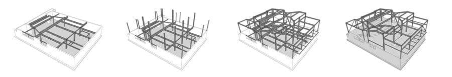
CAD/CAM has initiated an historical transformation of the building industry but is limited to linking design and manufacturing. Building Information Modeling (BIM) extends this to encompass the organization and management of all attributes of a project. This process is currently in its infancy and is only feasible on very large projects with fees to support the time necessary to input the vast amount of data associated with a BIM. This project set out to test alternative versions of BIM applicable to a wider range of projects.
Expanded Alliances
The practice of architecture has always been about managing information. Architects produce documents that coordinate the efforts of multiple constituents with the goal of designing buildings. With the availability of ubiquitous communication technologies, the rapid transformation of the building industry through these technologies and a new entrepreneurial spirit among a younger generation, architects are now in a position to leverage their expertise to actually design the organization of a project – to creatively and strategically assemble new alliances among owners, clients, builders, fabricators, consultants, etc. that lay the groundwork for innovative architecture.
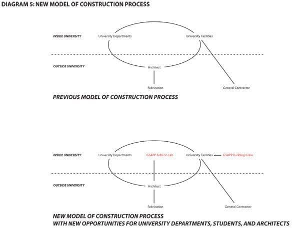
The University has two models of capital project developments – those done with an in-house design team from the Department of Design and Construction within the facilities department and those done with an architect hired by the university. The test project proposed and implemented a new model for campus projects. It required communication networks and exchanges that were well beyond those currently used in campus project development. It utilized both existing resources and expertise as well as new resources and expertise that were currently untapped by facilities.
As a first case study of New Alliances, the test project was created around the following conditions:
1. The school of architecture developed a fabrication lab (FABCON) to expand the ongoing interest in digital design and production tools & techniques. The lab consisted of a CNC mill and water jet machine backed up by a fully equipped work shop. The mandate of the lab is research new fabrication and assembly techniques at full scale.
2. The architects / professors utilized their established relationship with multiple constituencies in the university to gain support for a new organization to the structure of a capital project forming a new type collaboration between the client (the Department of Art History and Archaeology), the Department of Design and Construction within the facilities department, the School of Architecture, and the FABCON lab.
3. A master plan by the architects / professors for the client was in its early stages of implementation with one project complete and several others planned over the next few years. The test project became phase one of the master plan.

The Organization of Expanded Alliances
As both faculty members of the university and practicing architects, we set up a collaborative structure between the necessary academic and professional constituents to maximize the net results for all involved. The client department will get a highly unique design at a significant savings; the architecture school is able to give unprecedented opportunities for students to test new fabrication techniques in their fabrication lab (FABCON); the facilities department will be able to promote supporting innovative design projects on campus, and the university at large will benefit from sponsoring quality design through interdepartmental collaborations. In addition to the university affiliates, outside professionals were brought in as needed for their expertise and in some cases to expand the capacity for fabrication.
Test Project
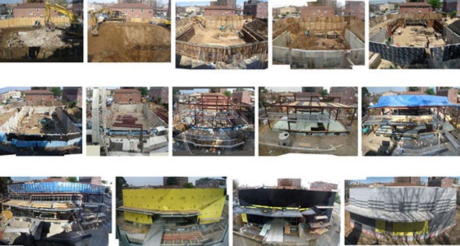
Site
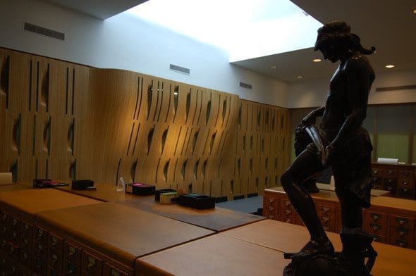
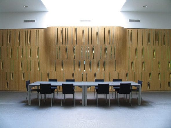
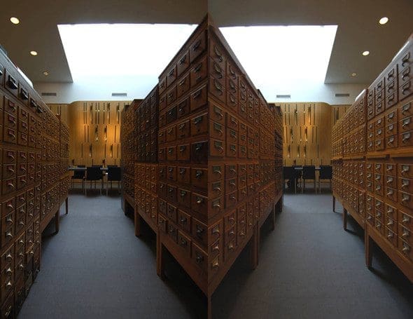
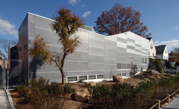
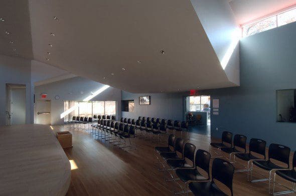
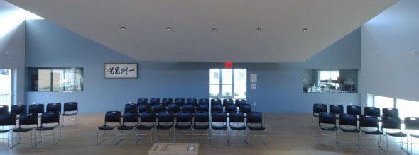
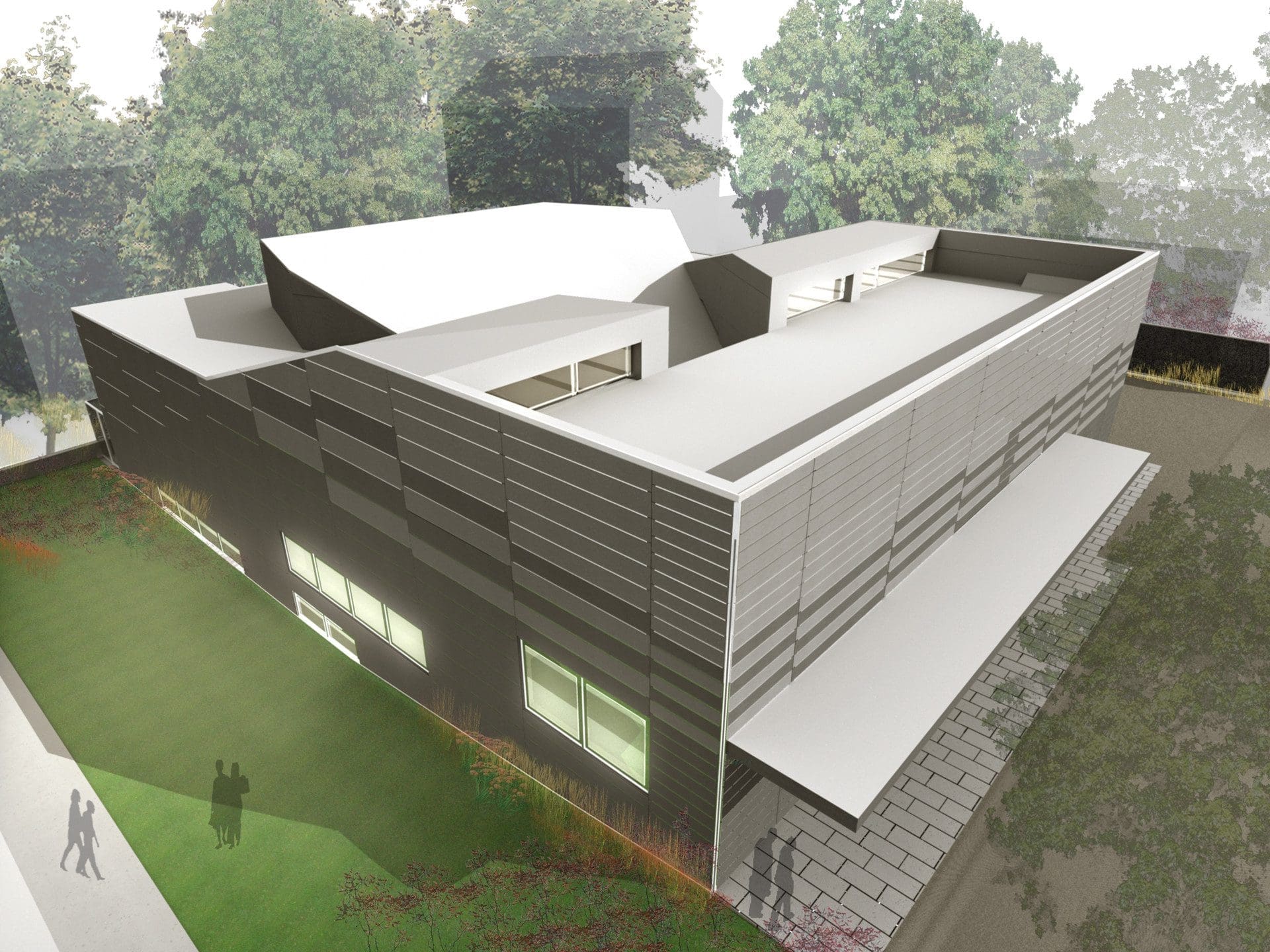
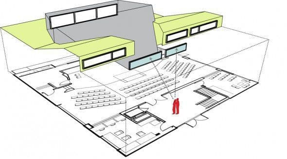
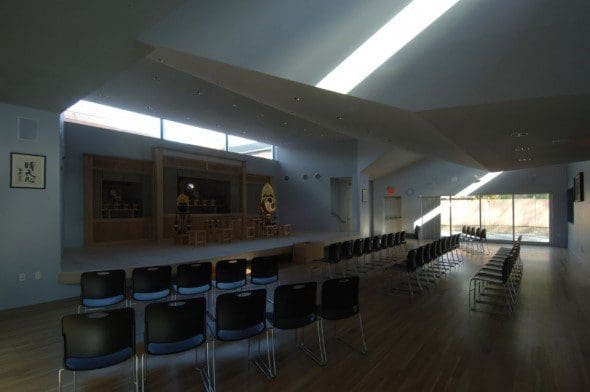
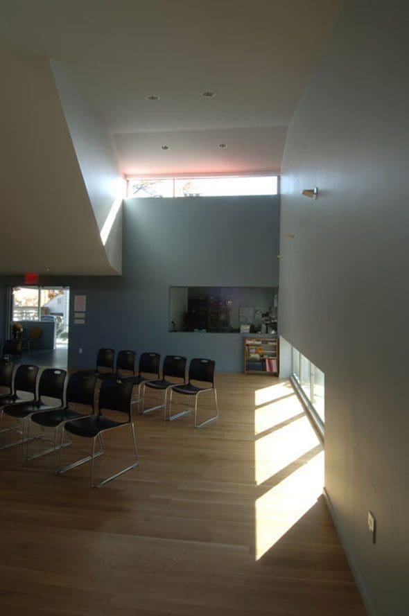
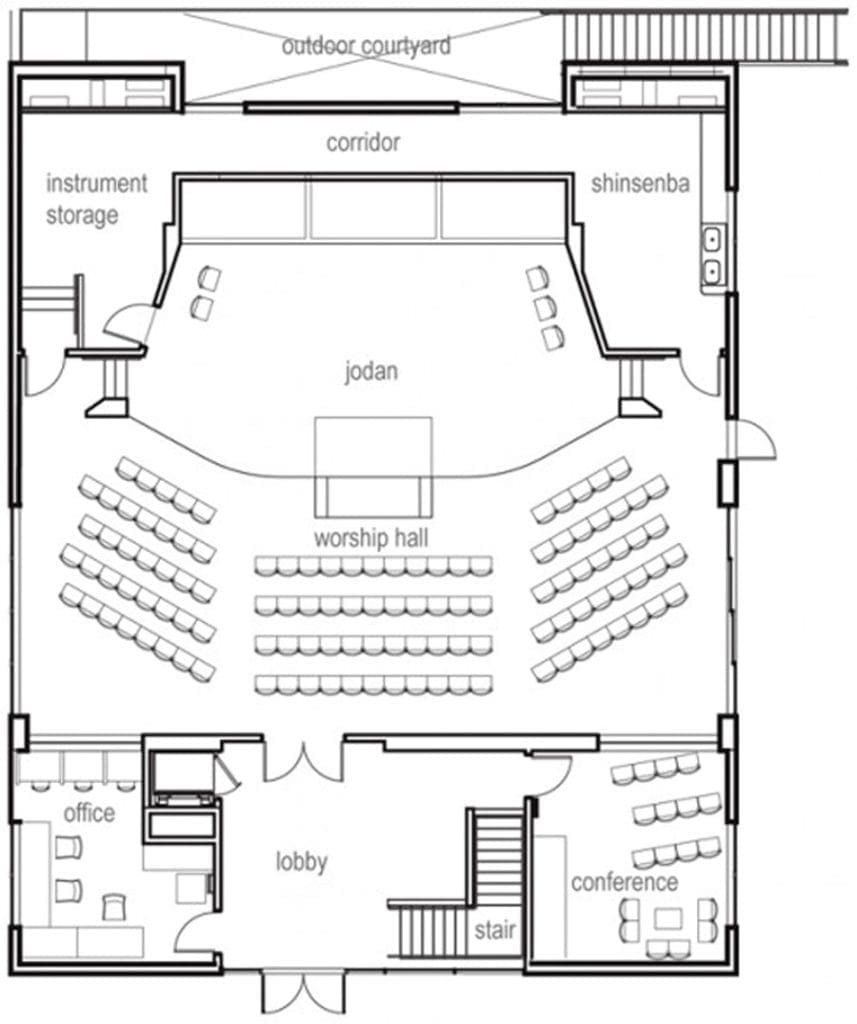
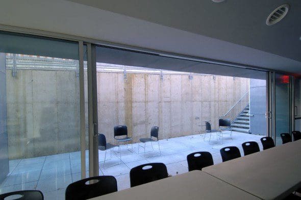
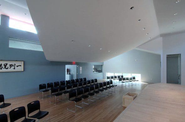
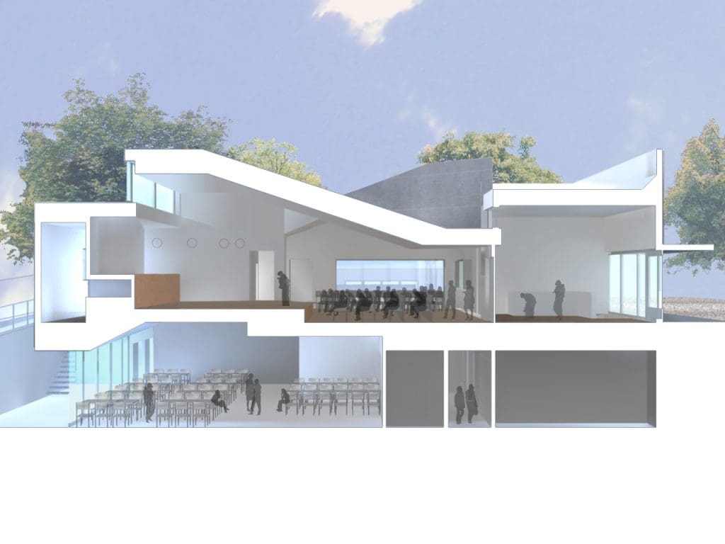
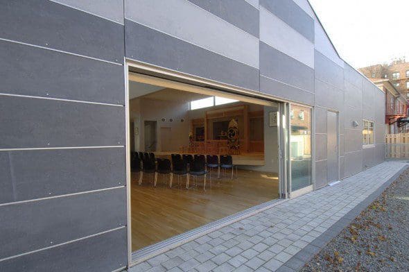
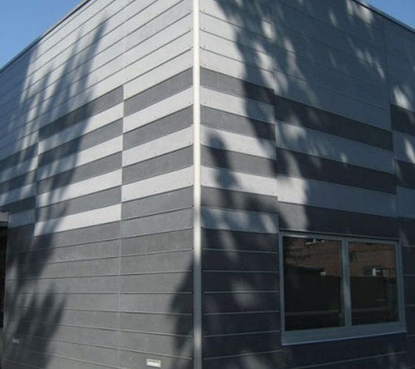
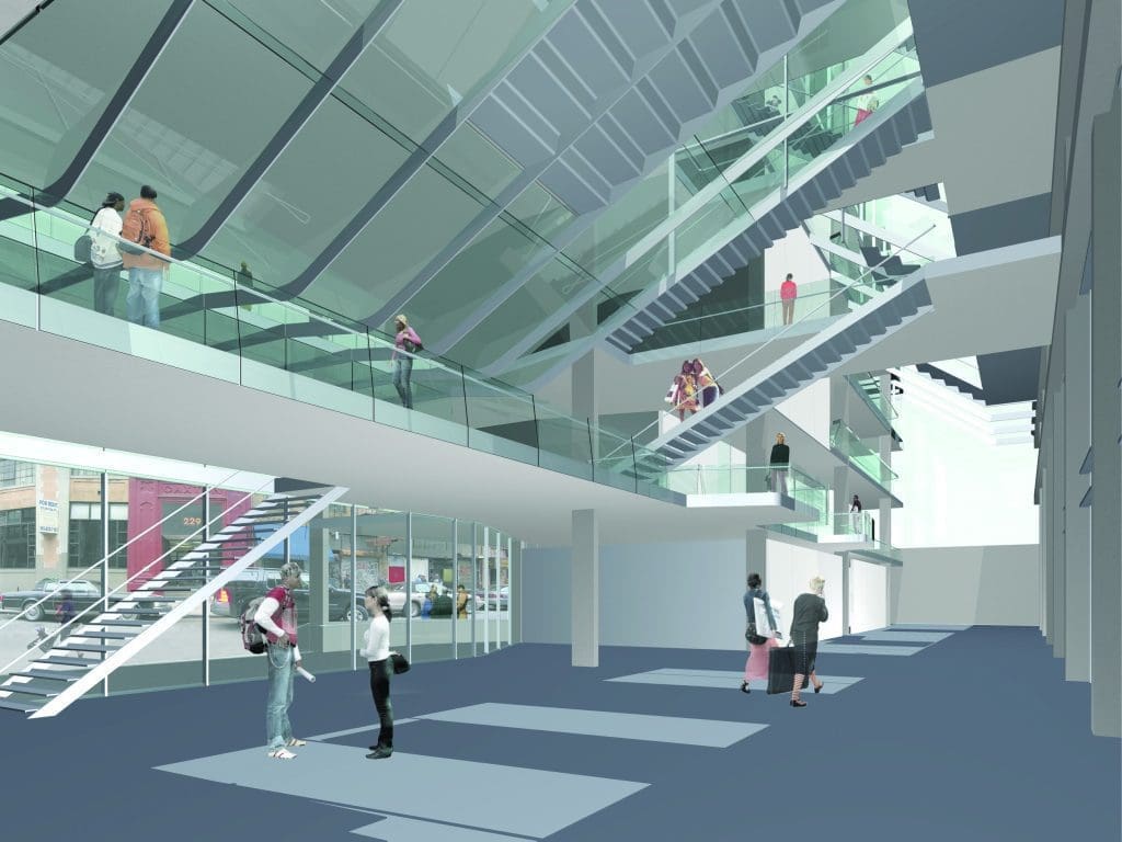
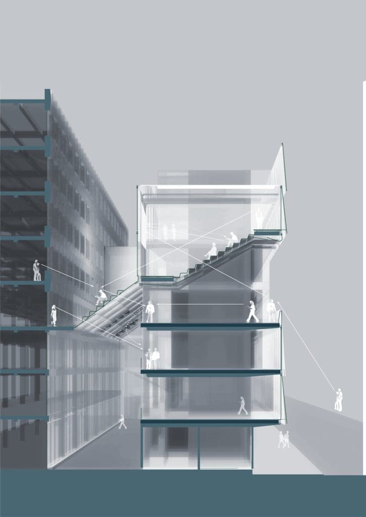
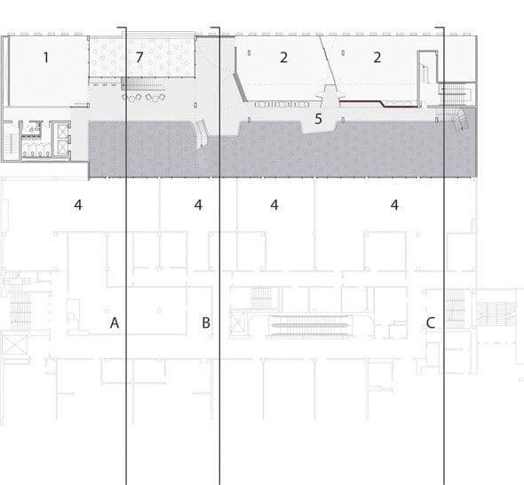
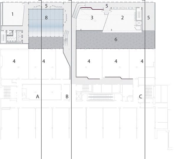
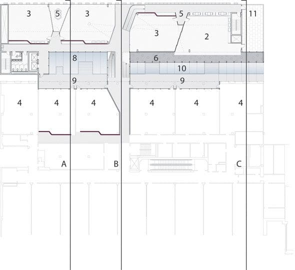
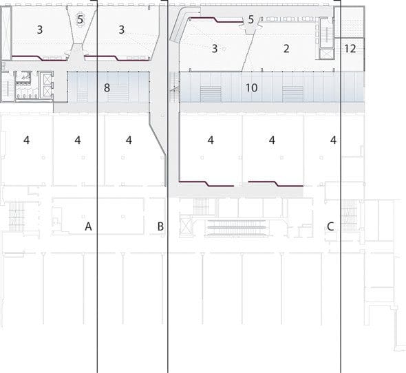
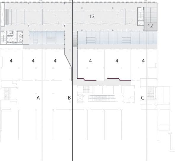
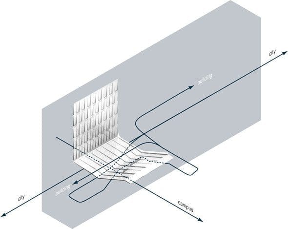
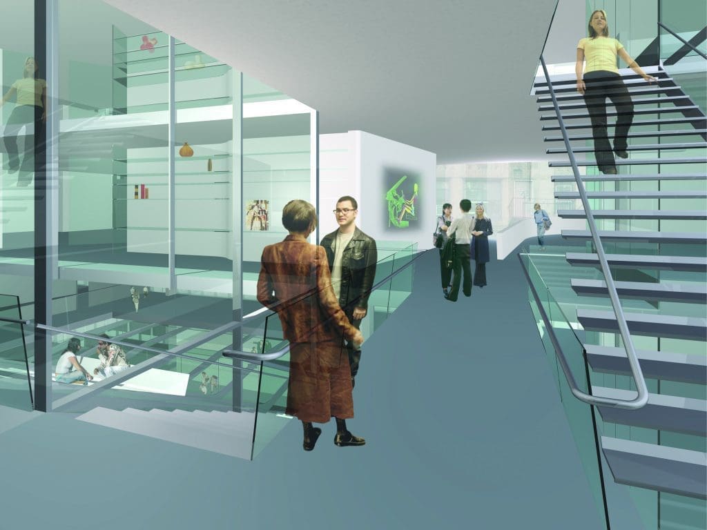
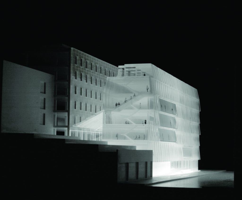
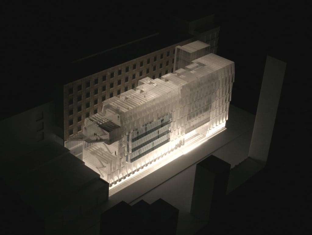
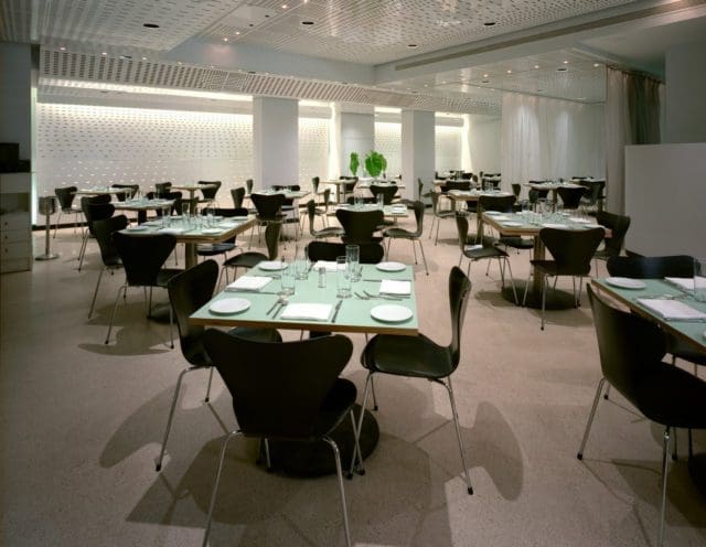
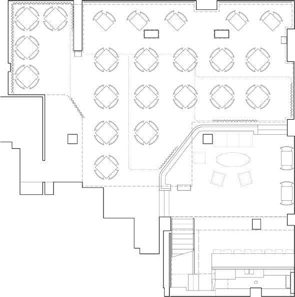
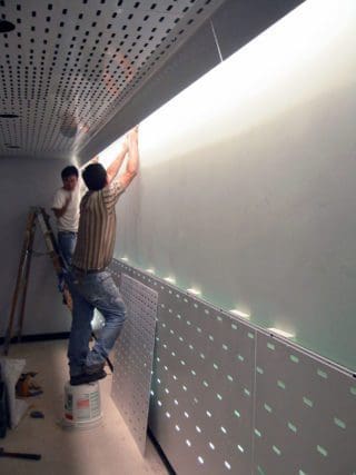
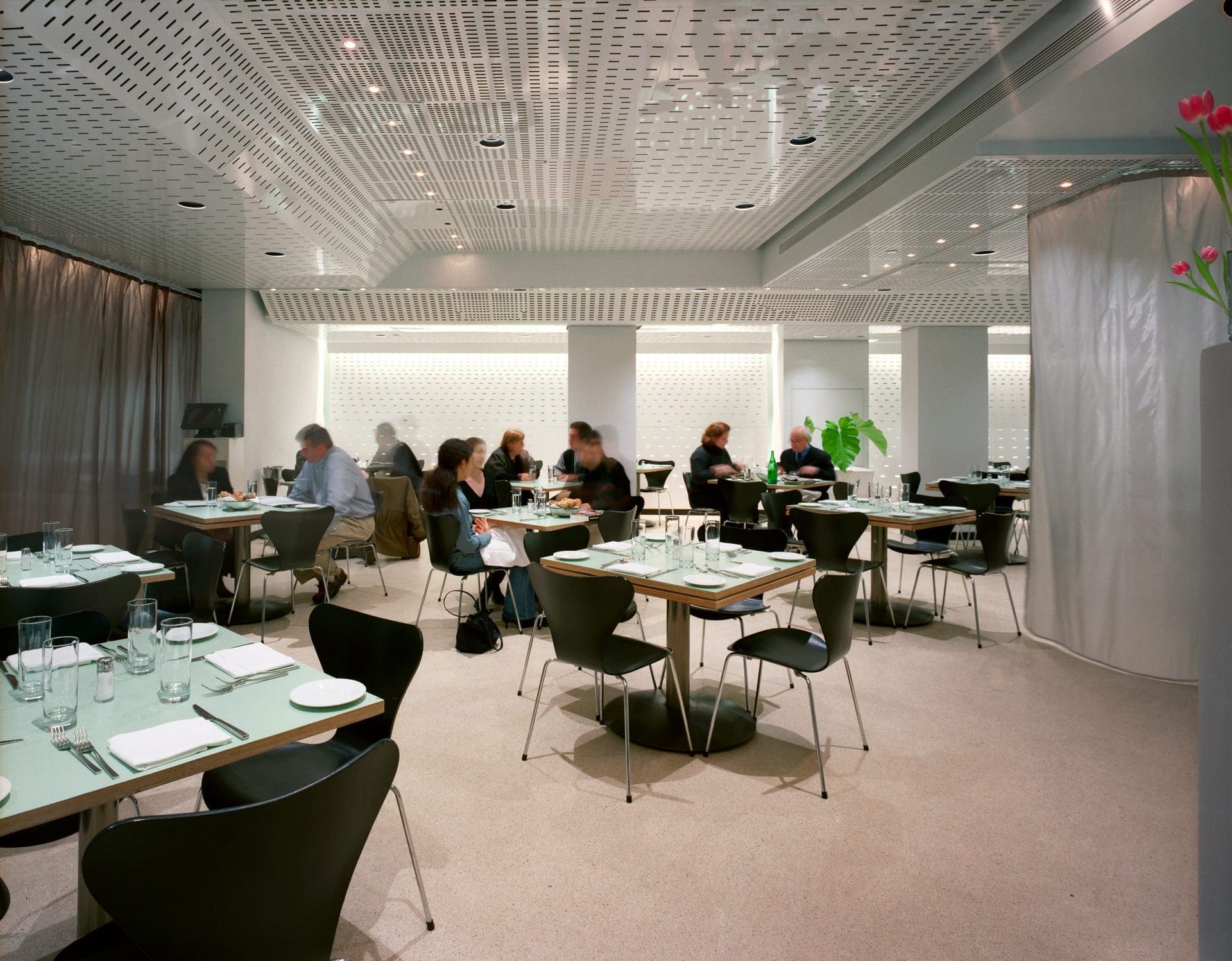
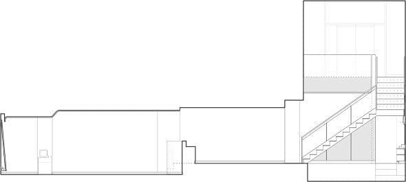
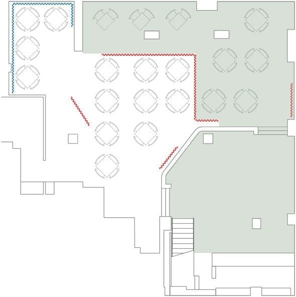
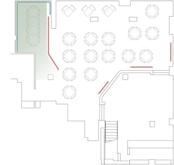
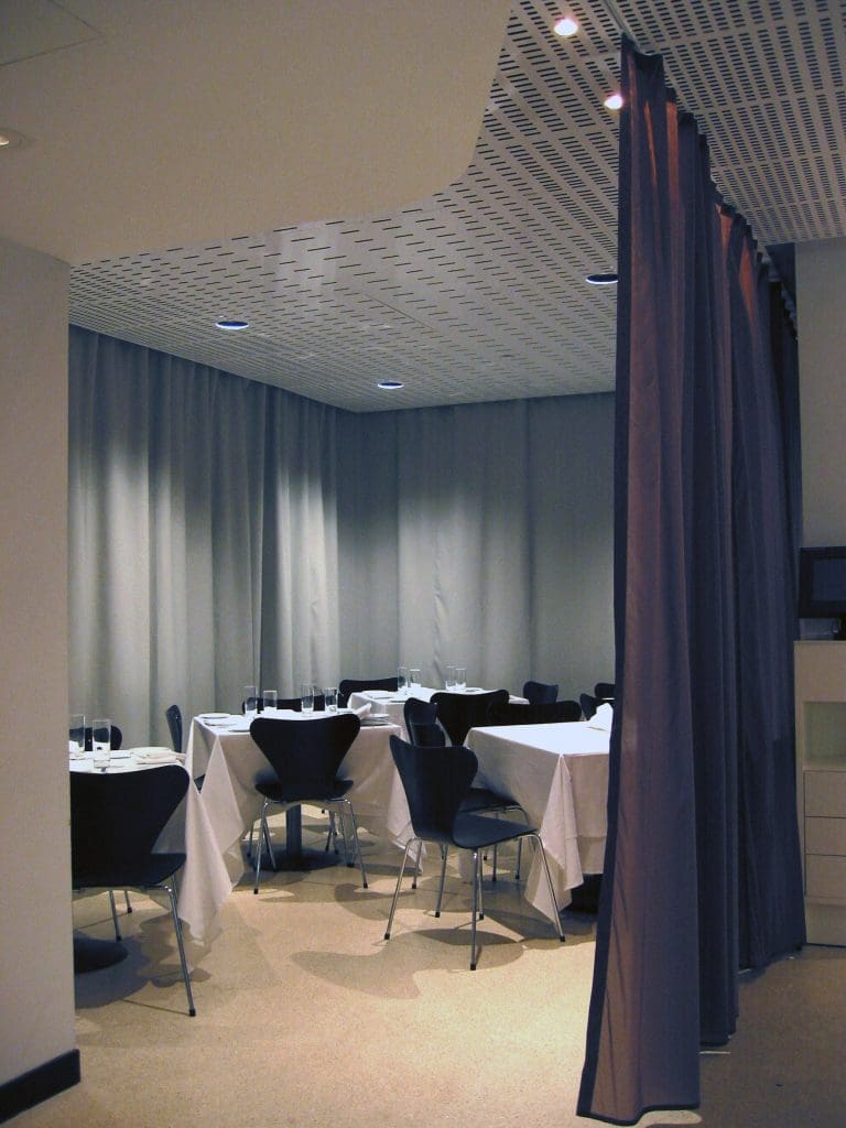
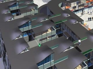
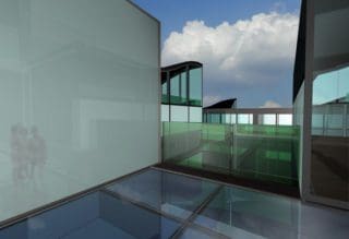
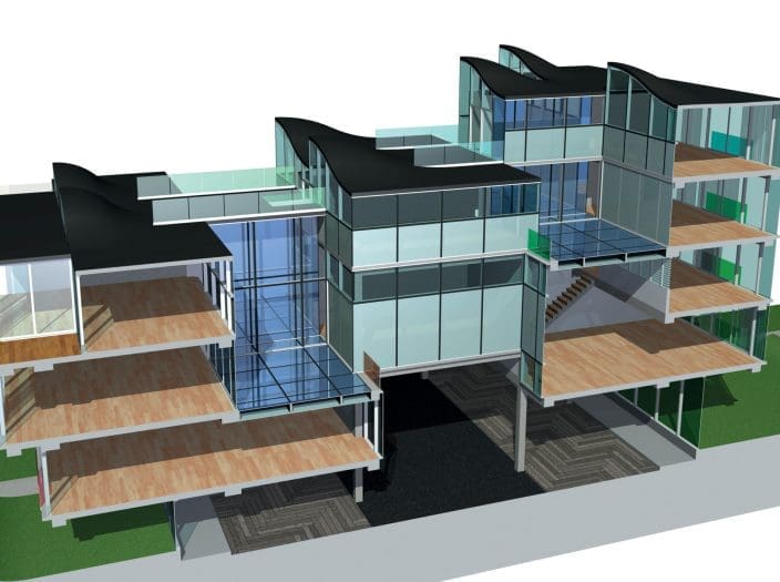
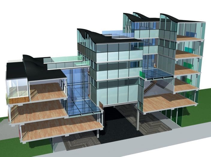
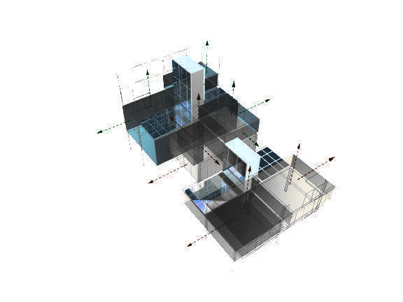
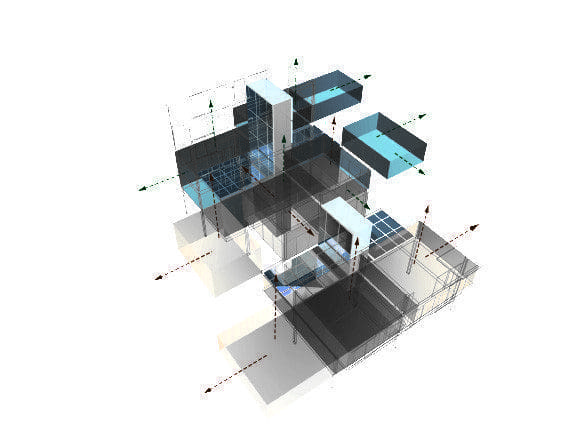
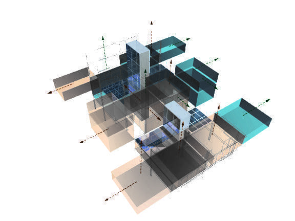
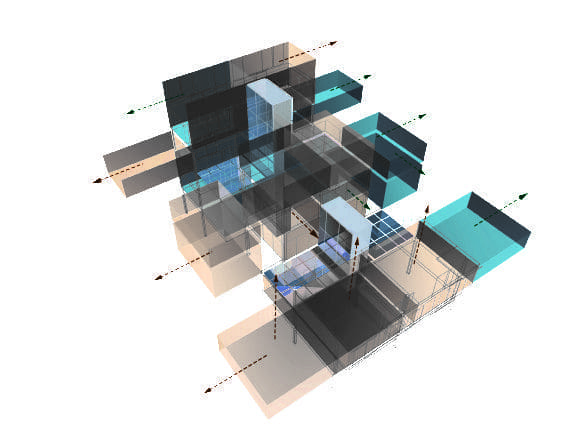
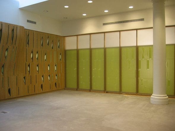
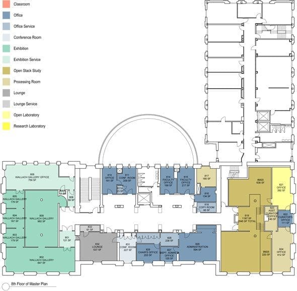
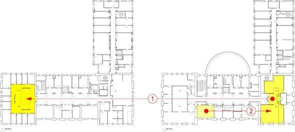
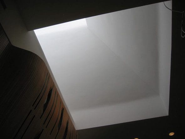
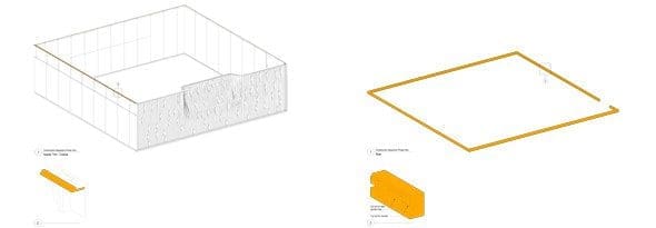
The Department of Art History and Archaeology undertook a space analysis and subsequent master plan to maximize its space utilization relative to current teaching trends. As part of this master plan, it was determined that the slide library, which has an extensive and notable collection and uses one of the largest rooms in the department, could be relocated. Although reduced in size to 1000 square feet, its importance within the department was still significant and required a well-designed space – this became the test project. The new location is on the top floor of a 9 story Beaux-Arts building, a space without windows but with a very large skylight that will act as a lantern on the interior. It is surrounded by faculty offices and will also function as an informal conference space. The area where the slide library was located will become a future test project and house a new multi-program “social hub”.
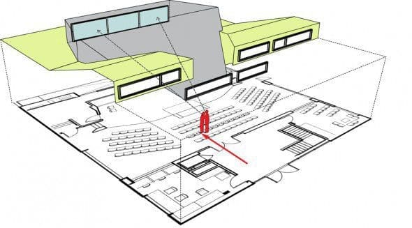
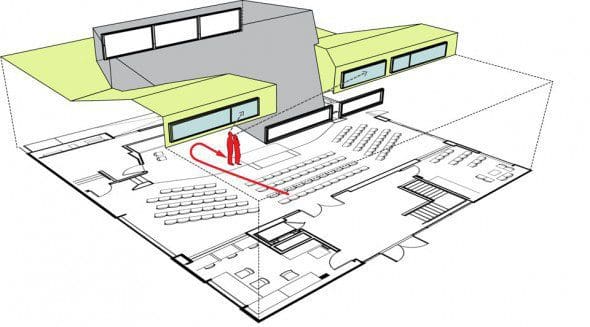
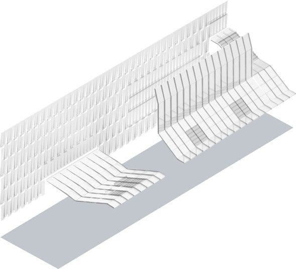
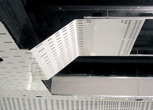
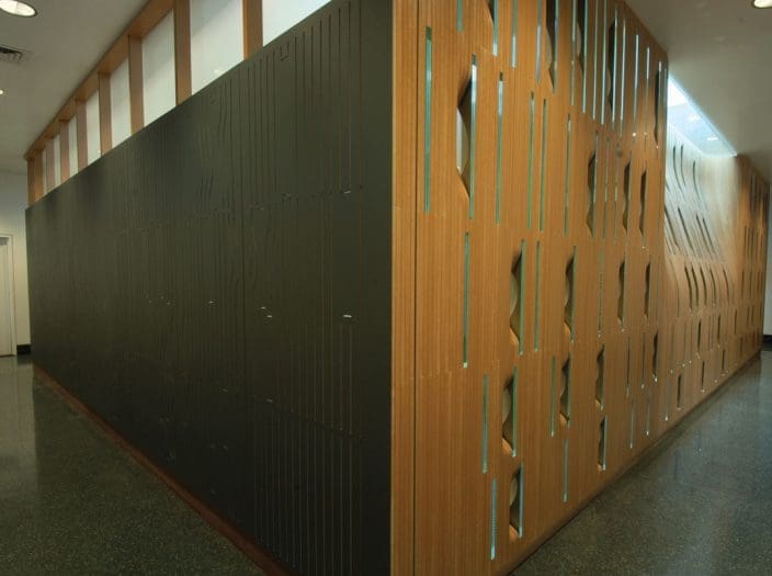
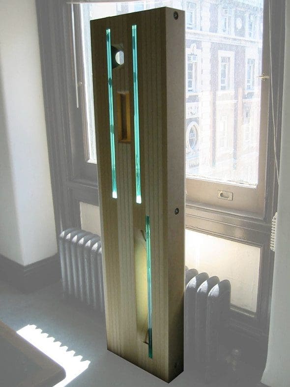
Slide Library
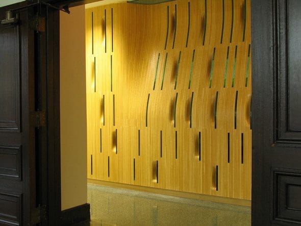
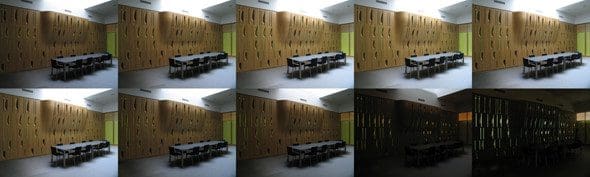
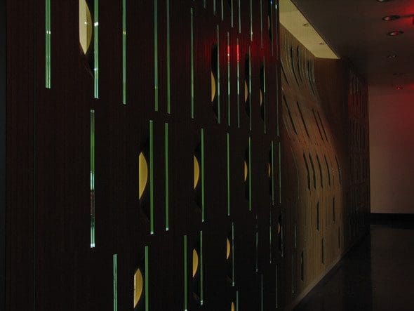
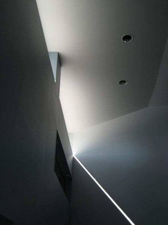
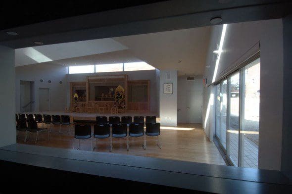
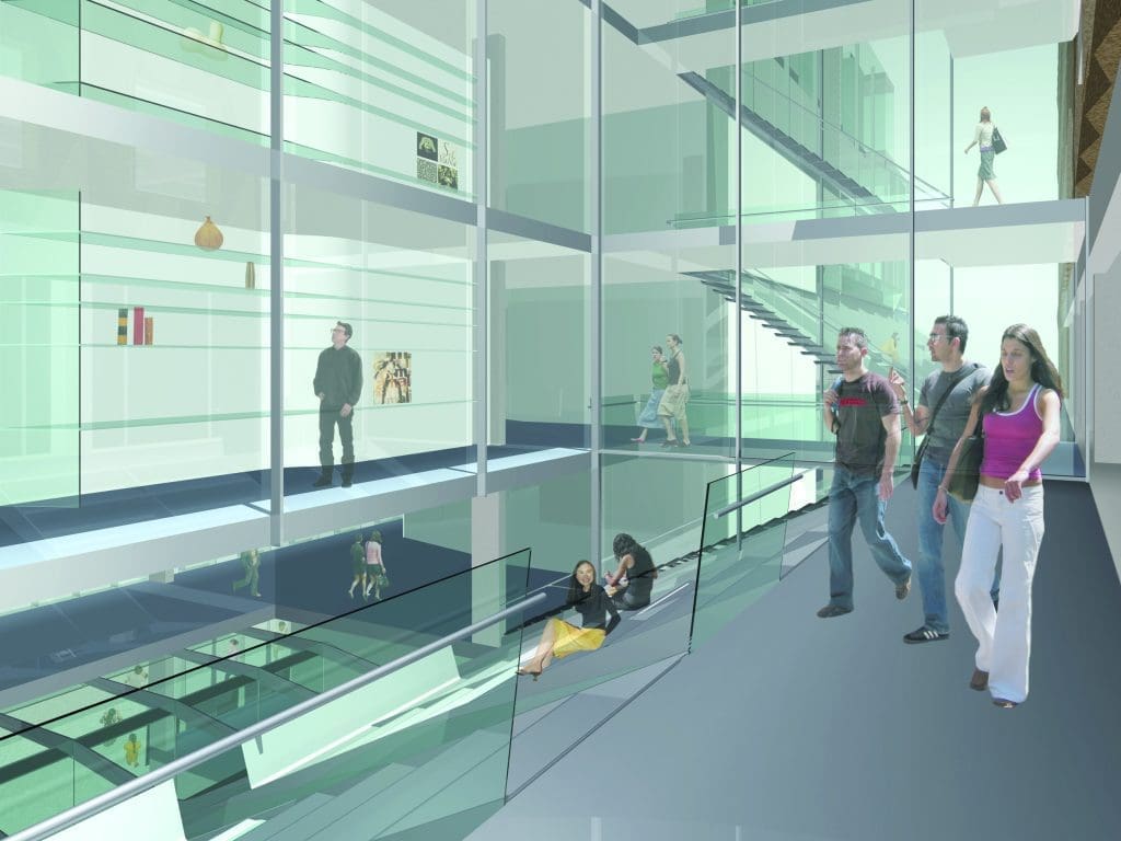
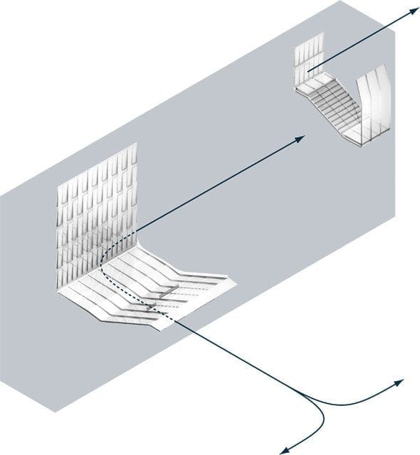
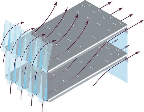
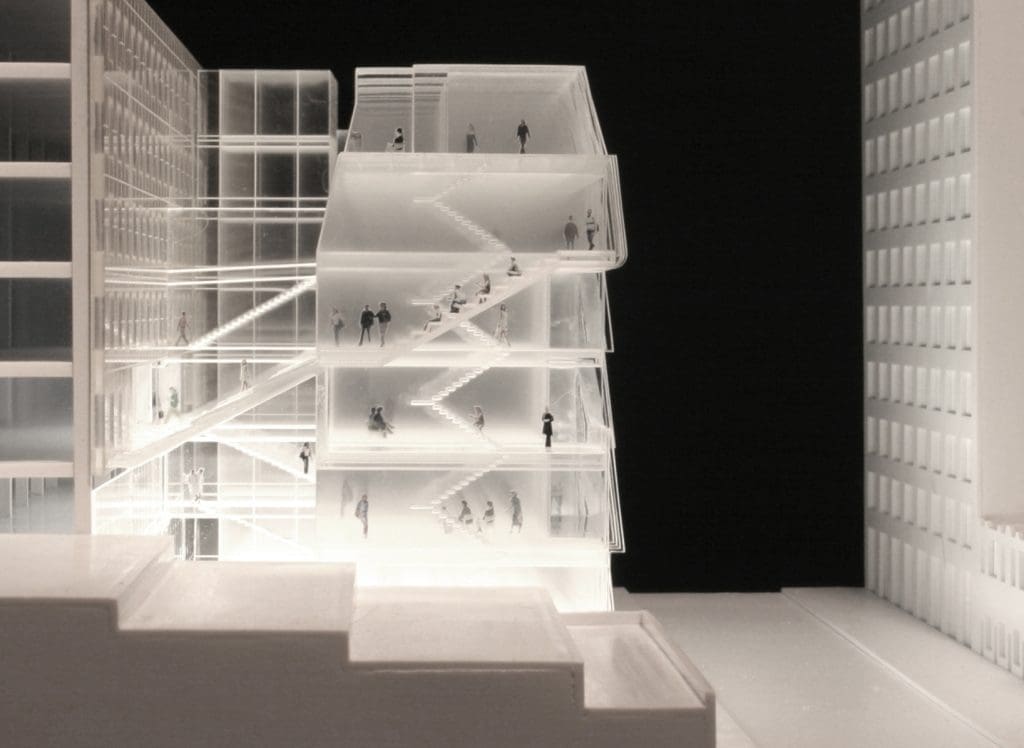
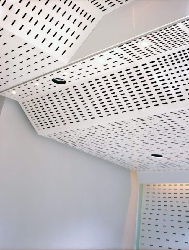
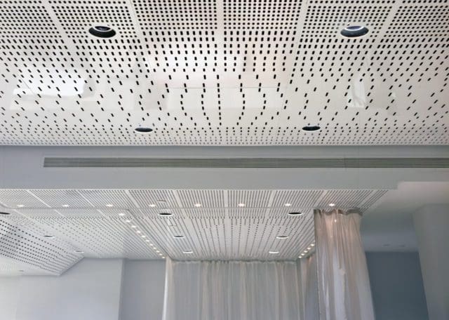
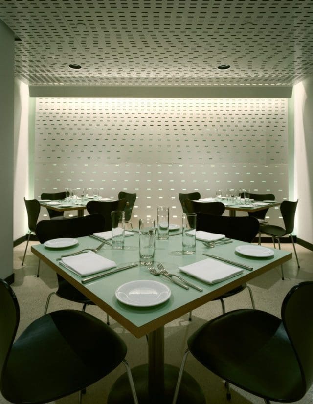
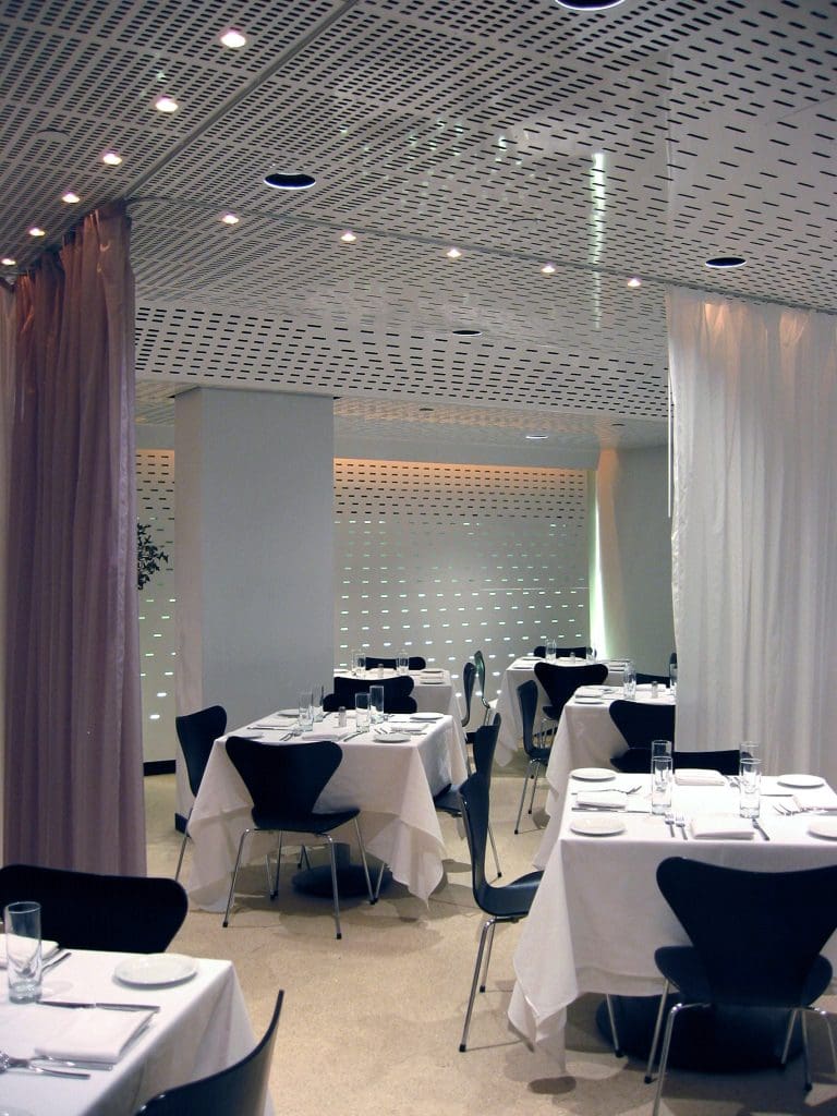
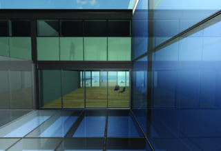
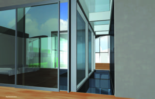
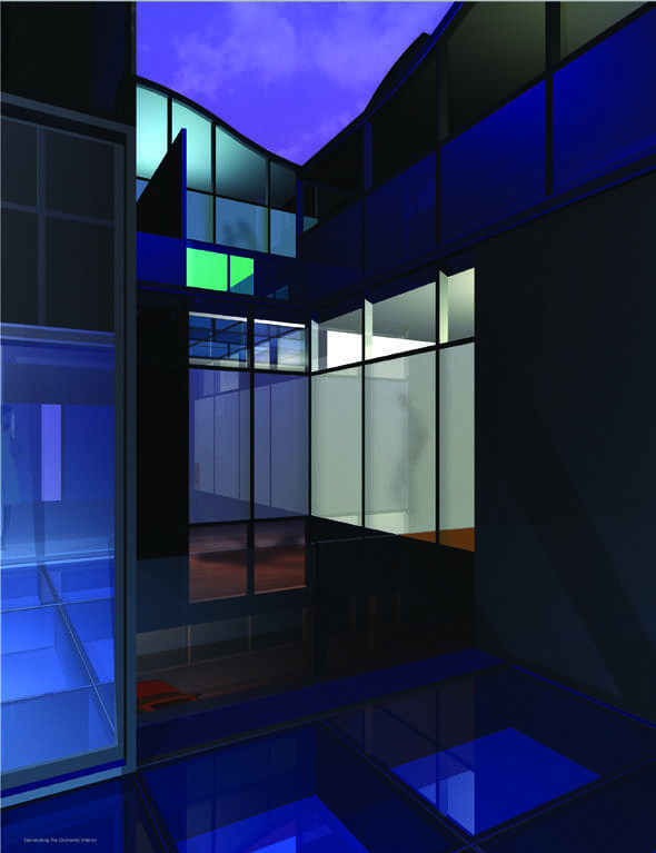
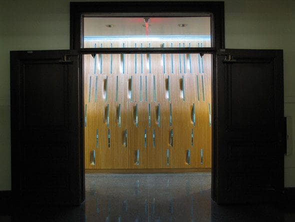
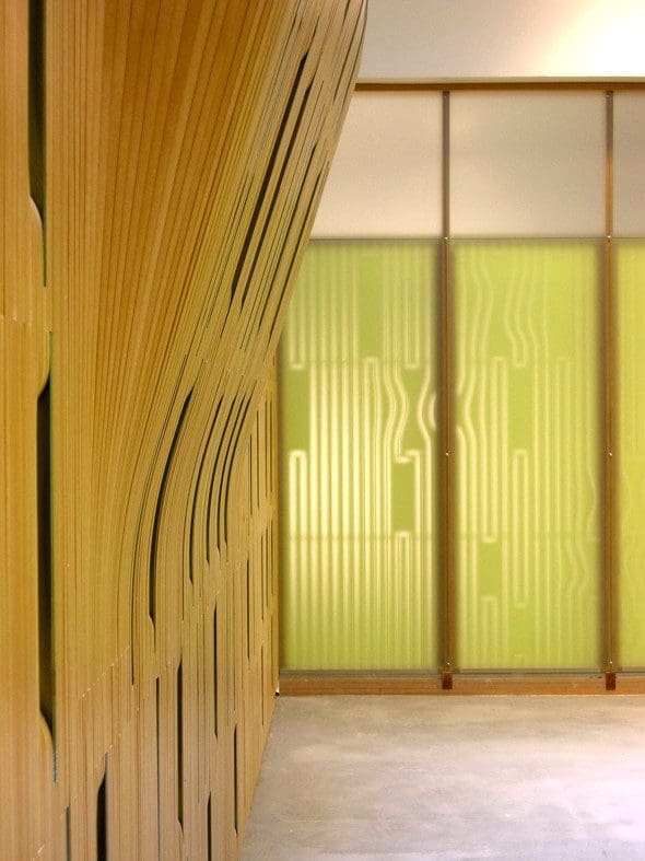
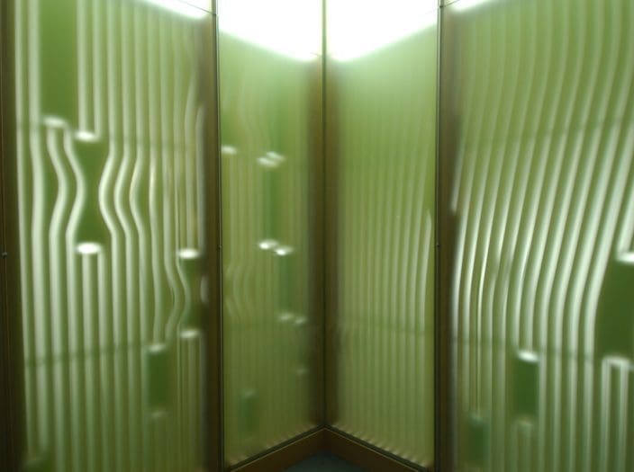
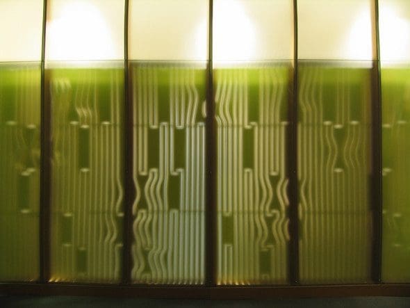
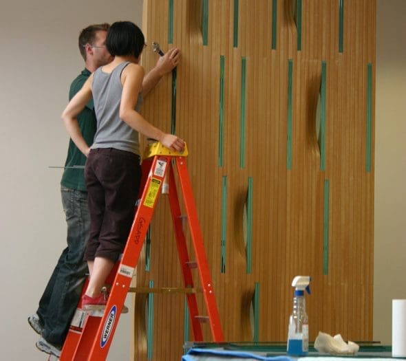
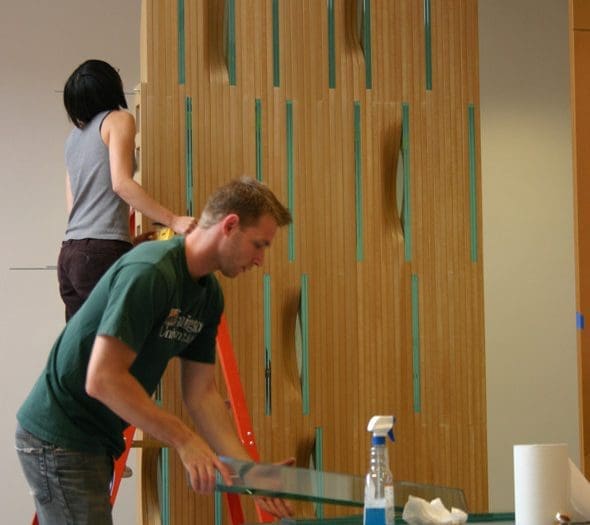
The slide library operates as both a didactic tool, describing the fabrication process through the information inscribed on its surfaces, and as a metaphor for the projector that illuminates the slides. The east wall is also curved to allow the skylight to directly light the hallway and the front of the slide library. Glass pieces embedded in the wall further transmit light from the interior of the slide library to its exterior. The captured light from the skylight is registered on and transmitted through the surfaces of the slide library in patterns that continually shift.
A large existing skylight was uncovered and integrated into the design, bringing light into this otherwise completely interior space that is surrounded by faculty offices.
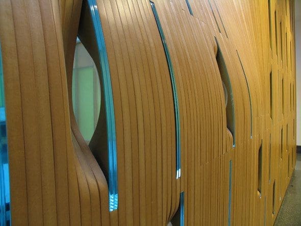
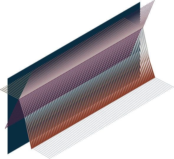
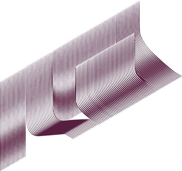
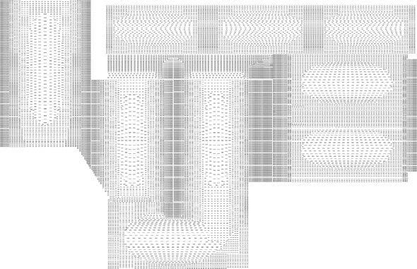
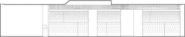
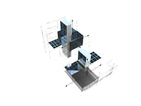
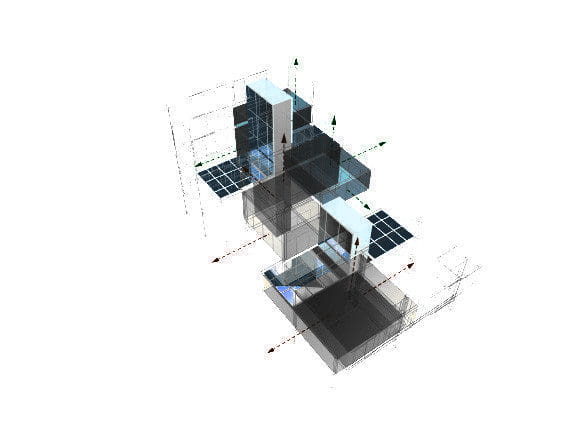
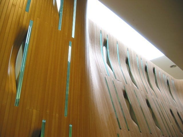
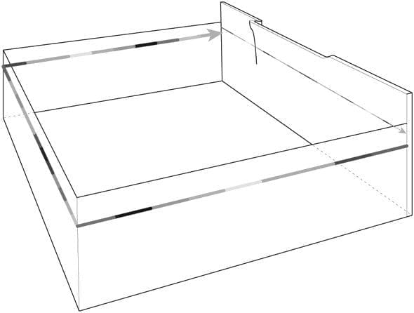
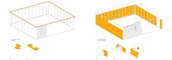
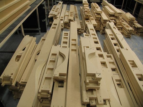
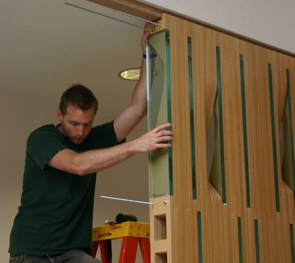
The east wall is made up of 435 layers of ″ thick ultralight (lightweight MDF) sandwiched together. Occasional viewing portals are formed by carved layers on opposite sides of the wall with two 1/2″ thick glass panels sandwiched between them. The drawing shows how the toolpaths that were used to mill the layered (east) wall were laid out and milled into north, south and west walls.
Prototypes
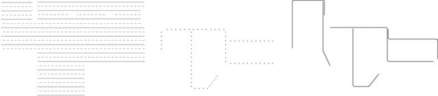
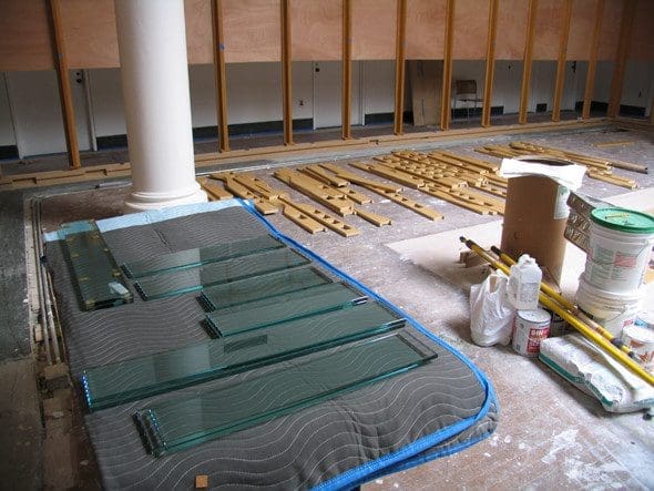
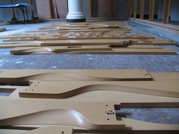
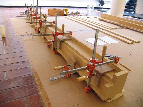
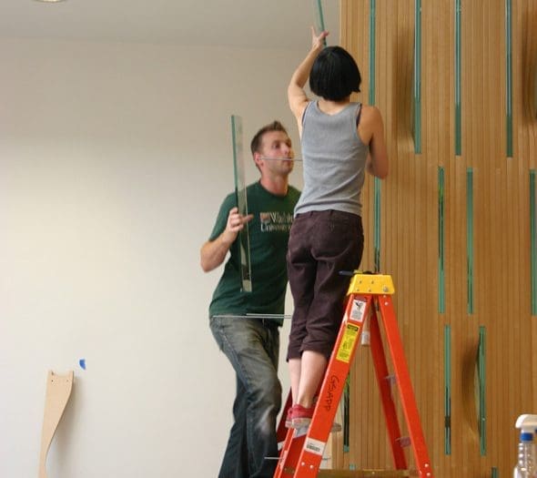
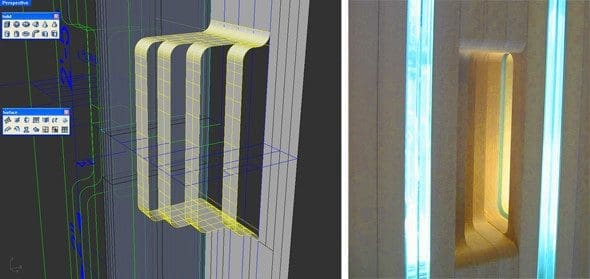 Several full-scale prototypes of the portals were fabricated and assembled. Different milling techniques were tested from straight cuts to curved profiles on each of the 1” layers to study the effects of the light and the experience of viewing through the wall. The geometry of the curves was flipped around the axis of the glass panels to form an overlap that allowed views through the wall.
A continuous curve was selected over stepped options – testing the precision of the mill to generate smooth curves over multiple layers of the 1” ultralite. This also required some of the layers to be milled on both sides due to the limitations of 3 axis CNC mills to undercut. Techniques were tested to calibrate the precision of alignments when flipping the panels. During these tests, it was also determined that the existing floor structure would not support the wall so cavities were milled inside the wall to reduce the overall weight.
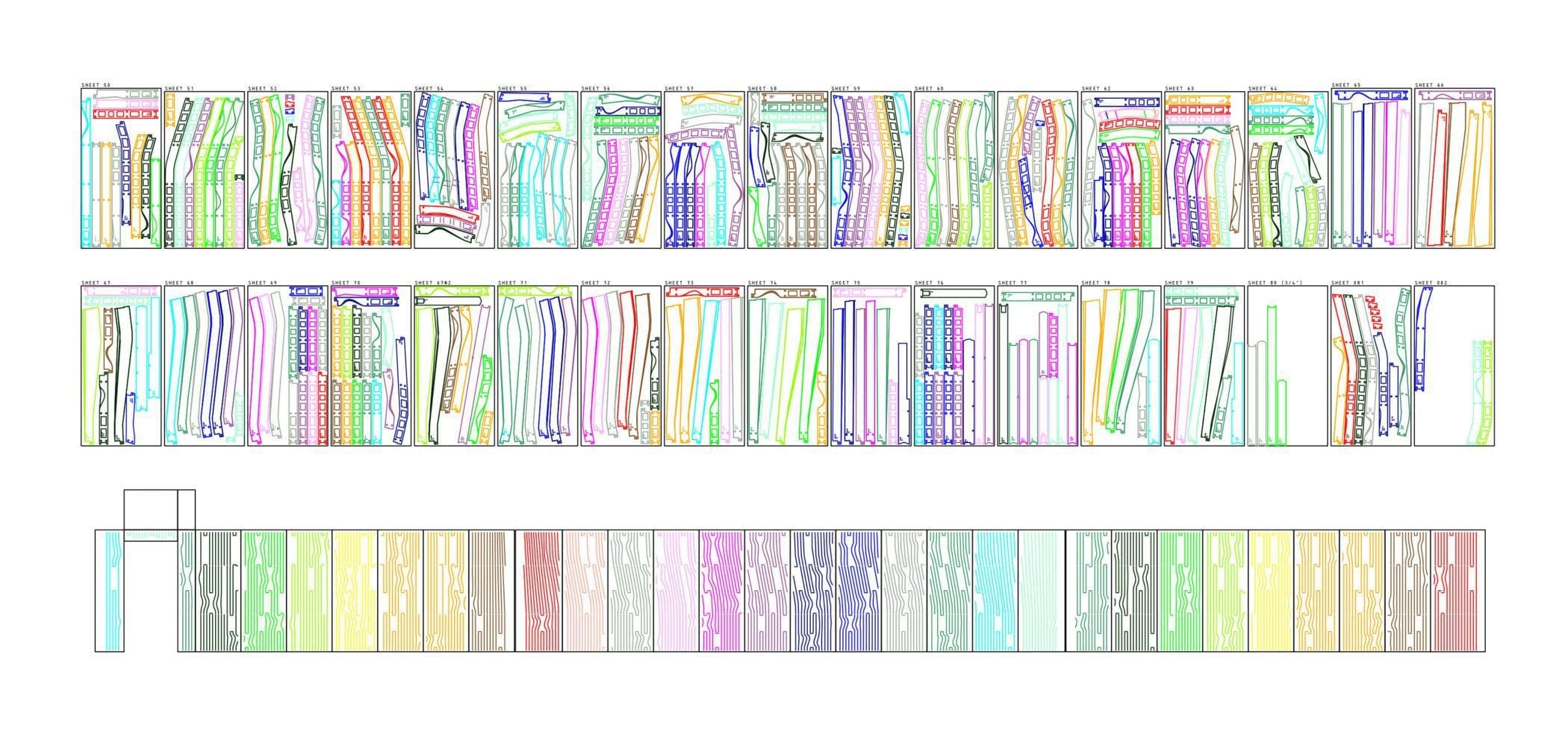
Layered Wall Tool Paths
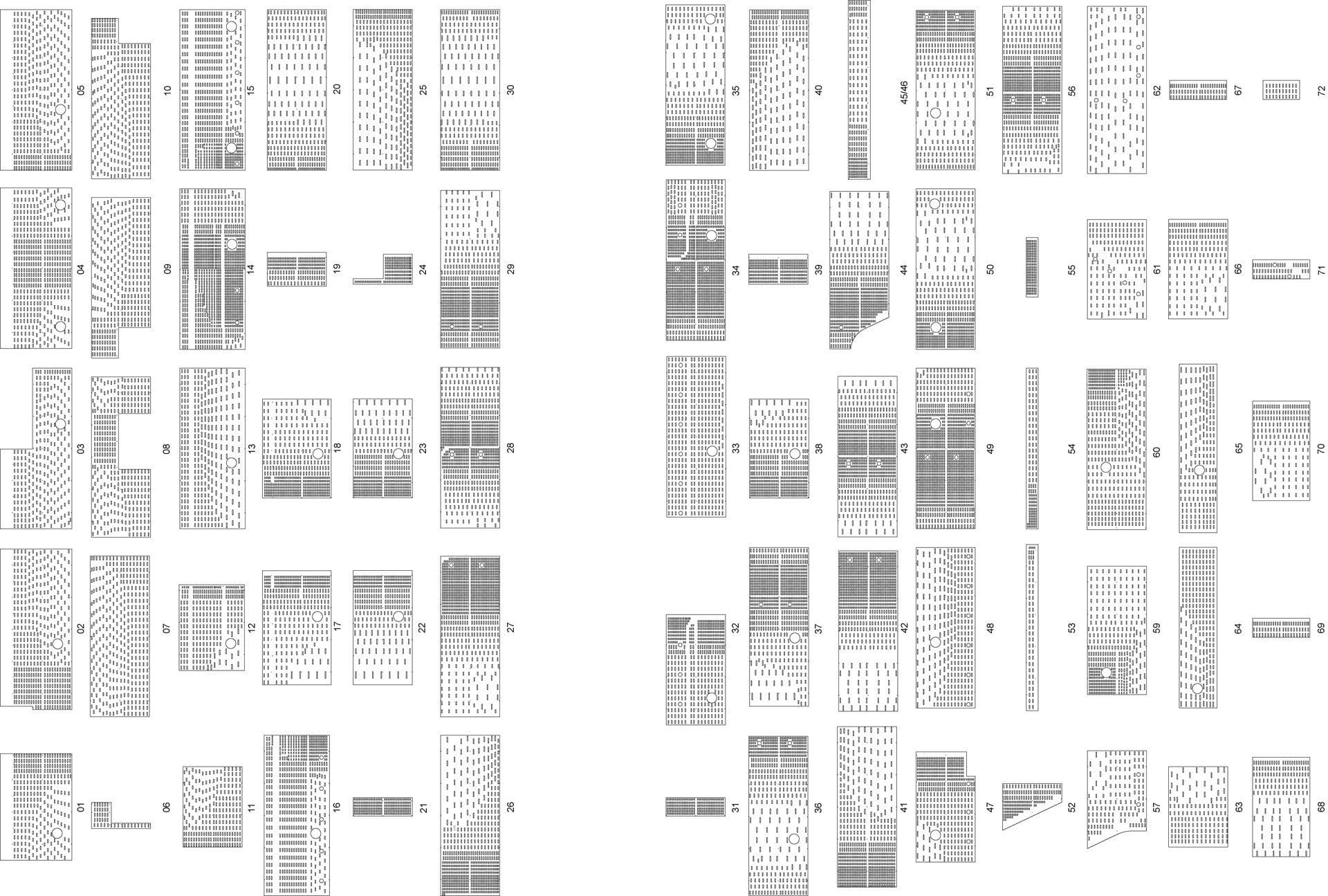
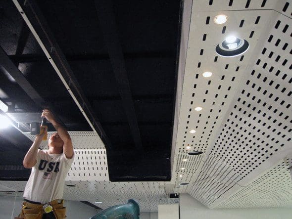
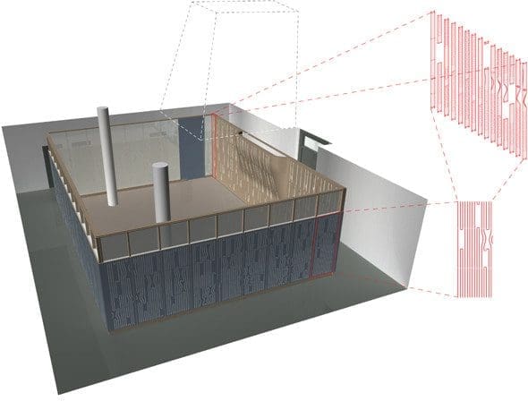
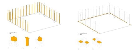
As part of the rigor to digitally draw, fabricate and manage the entire project, every component of the design was milled regardless of its complexity to enable the walls to be assembled like furniture. A material limitation was imposed to control the variables – mdf was used for all components. The structural columns on the north, south and west walls were designed as interlocking components with coordinated slots to receive all glass.
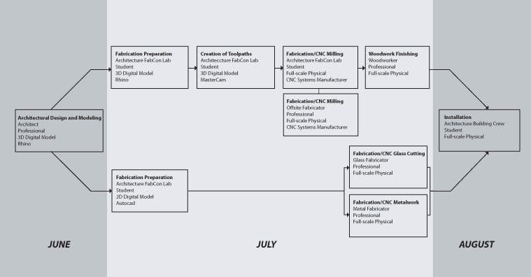
A 3-axis mill was used for all components. Because the project was relatively small and one of the goals of the test was to simulate the complexity of building information management on a larger scale, the intricacies of the walls were exaggerated. Another goal of the project was to test the agility of digital information to adapt to unforeseen circumstances. When the milling for the components was calculated for a single machine and found to be longer than the duration of the project, instead of simplifying the design, the network of fabricators was expanded to increase the workflow with little impact on the coordination.
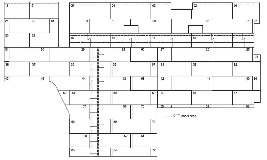
Material management: Related to individual components making up a larger component along with the sequence of assembly was coordinated through a comprehensive labeling index that went from design through final installation.

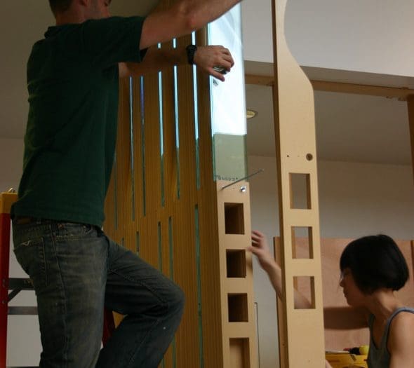
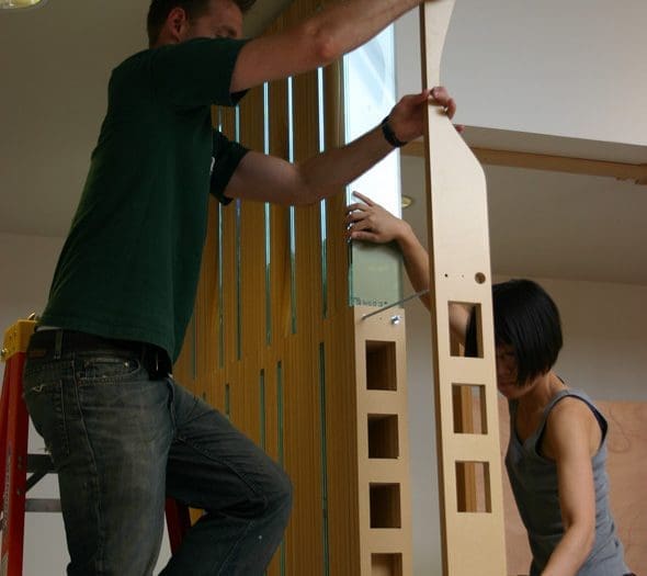
Assembly: North, South, & West Walls
Many of the typical construction drawings become redundant with a building information management project. Drawings for this test project existed only for the purposes of describing the sequence of assembly. Minimal notes and no dimensions were used as emphasis was placed on communication through graphic clarity.
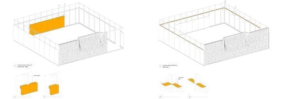

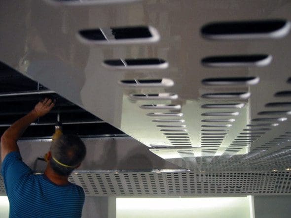
Assembly: East Wall
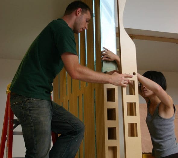
The assembly of the east wall was kept as simple as possible relying only on a linear numbering sequence for each of the layers and an attachment method of staggered 18” long threaded rods connected with threaded couplings. The glass was held in place with the compression from the rods and required no adhesives. A top and bottom track held the wall in place. Students assembled the east wall in one week.
Workflow
University projects typically take place over the three months of summer break requiring a well-coordinated and expedient workflow. Through a close interactive collaboration between architect, fabrication team, project manager, general contractor all entrusted by the client, this test project fulfilled all of its goals of design, prototyping, fabrication and assembly on time and on budget.
The Future
Schools of architecture pioneered the first digital revolution through exhaustive formal experimentation and elaborate visualizations of these new forms. Many architecture students trained during this time were hired by digital animation, web design, advertising companies because of their unique skills to think, visualize and model complex form. While this was occurring, the construction industry was focused more on streamlining the manufacturing and building processes through CNC technologies with little or no emphasis on innovation beyond efficiency. The core goal of Expanded Alliances is to foreground the potential and urgency of a younger generation of architects to begin pioneering the second digital revolution in architecture. Because this revolves around actual building itself, the only effective way to do this is to build…at full scale. More importantly is the application of digital technology as a tool of communication to generate the organization of projects, to form networks of collaborators to realize projects and finally to design, manage, fabricate and assemble innovative architecture.